
Manual plate cutting machine

a cutting machine and manual technology, applied in the direction of metal working equipment, etc., can solve the problems of affecting the pressing effect, affecting the cutting effect, so as to improve the cutting force, improve the cutting effect, and improve the structur

Inactive Publication Date: 2017-07-13
XU WENSHENG
View PDF7 Cites 2 Cited by
  • Summary
  • Abstract
  • Description
  • Claims
  • Application Information

AI Technical Summary

Benefits of technology

The present invention is a manual plate cutting machine that is easy to carry and use. It has a stop block and a limiting groove that work together to prevent the handle from rotating too much. This helps to increase the lifespan of the machine and the workpiece. The front end of the handle and the front end of the cutter holder are in gear shape, which allows them to rotate synchronously. The handle can automatically drive the cutter to lift, and no reset spring structure is required, making it simpler and easier to use. Overall, the invention is designed to provide a better cutting experience and make it simpler to cut plates.

Problems solved by technology

The electric plate cutting machines produce great noise and serious powder contamination, which are mainly used in the large-scale production; while a manual plate cutting machine is easy to carry, when paving floor boards, it can achieve cutting of floor boards according to the processing size.
Since the contact between the eccentric cam and groove relies on an arc surface, a prolonged use will produce wear, affecting the pressing effect.
A prolonged use of the reset spring will produce unrecoverable deformation, affecting the effect of reset of cutter holder and causing inconvenience for cutting.

Method used


Image

  • Manual plate cutting machine
  • Manual plate cutting machine
  • Manual plate cutting machine

Examples


example 1

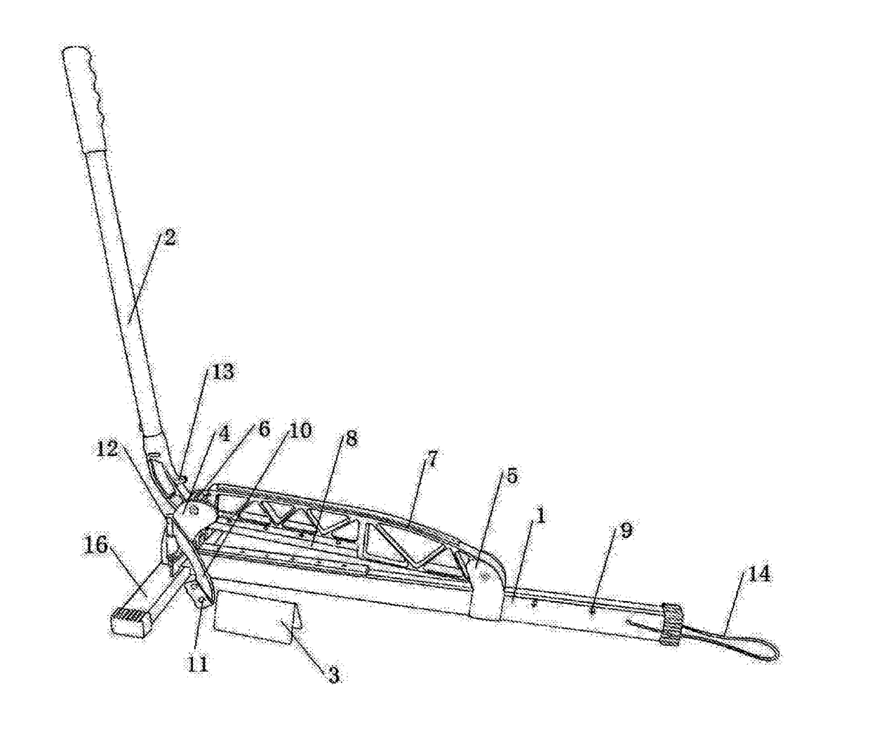
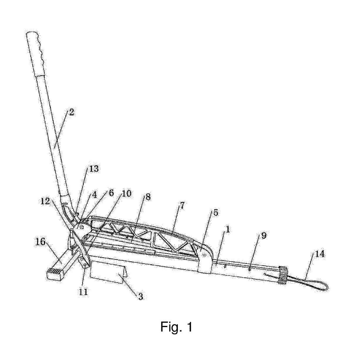
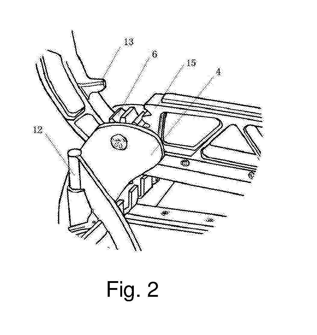
[0017]A manual plate cutting machine comprises a workbench 1, a handle 2 and a cutter. In example 1, the workbench 1 is rectangular and cylindrical. The front end of the workbench 1 is provided with a fixed base 16, which is detachable from the workbench 1. A front support 4 and a rear support 5 are mounted at regular intervals on the workbench 1 and along the extending direction of the workbench 1. One end of the handle 2 is in gear shape, which is an active sector gear 6; and the active sector gear 6 is in shaft connection with the front support 4 and it can rotate around the front support 4. The cutter comprises a cutter holder 7 and a cutter body 8. The cutter body 8 is mounted below the cutter holder 7, and one end of the cutter holder 7 is in a gear shape, which is a passive sector gear 15, engaged with the active sector gear 6, and the other end of the cutter holder 7 is in shaft connection with the rear support 5, to rotate around the rear support 5.

[0018]When cutting, raisi...

example 2

[0021]Different from example 1, the manual plate cutting machine further comprises a support frame 3 with the same height as the workbench 1, and a support frame suspension mechanism 9 is provided at the sidewall of the workbench 1. In example 2, two suspension holes are provided at the sidewall of the support frame 3. The support frame suspension mechanism 9 is two axial protrusions with the equal distance from the suspension holes, and the suspension holes can hung on the axial protrusions.

[0022]Further, the manual plate cutting machine still comprises a plate clamping mechanism which includes a clamping plate 10 in shaft connection with the workbench 1 through a clamping plate mounting shaft 12, and the clamping plate can rotate around the clamping plate mounting shaft 12.

[0023]The thickness of floor boards varies, including 8 mm, 10 mm, 12 mm, 15 mm, 18 mm, etc. To make the clamping plate 10 to secure floor boards of different thickness, an elastic member 11 is mounted at the lo...


PUM


Abstract

A manual plate cutting machine, comprises a workbench, a handle and a cutter, a front support and a rear support mounted on the workbench at intervals, wherein one end of the handle is in a gear shape, which is an active sector gear, coupled with the front support; the cutter comprises a cutter holder and a cutter body, the cutter body is mounted below the cutter holder, and one end of the cutter holder is in a gear shape, which is a passive sector gear, engaged with the active sector gear, and the other end of the cutter holder is coupled with the rear support. The present application optimizes the structure of a manual plate cutting machine. Compared with the traditional machine with reset spring structure, when cutting the plate, it is not required to overcome the elastic force of the reset spring, making it easy to cut.

Description

CROSS-REFERENCE TO RELATED APPLICATION[0001]This application claims the priority benefit of Chinese application serial no. 201620021827.5, filed on Jan. 11, 2016. The entirety of the above-mentioned patent application is hereby incorporated by reference and made a part of this specification.FIELD OF THE INVENTION[0002]This present application relates to a cutting device, in particular, to a manual plate cutting machine.BACKGROUND OF THE INVENTION[0003]Plate cutting machines can be divided into two types: manual plate cutting machines and electric plate cutting machines. The electric plate cutting machines produce great noise and serious powder contamination, which are mainly used in the large-scale production; while a manual plate cutting machine is easy to carry, when paving floor boards, it can achieve cutting of floor boards according to the processing size. The workload for cutting is not heavy, thus, usually a manual plate cutting machine is used.[0004]The patent (application n...

Claims


Application Information

Patent Timeline
Patent Type & Authority Applications(United States)
IPC IPC(8): B26D5/10B26D7/02
CPCB26D7/025B26D5/10B26D1/305
Inventor XU, WENSHENG
Owner XU WENSHENG
Learn More