Brake control system

Inactive Publication Date: 2017-07-13
HITACHI AUTOMOTIVE SYST LTD
View PDF1 Cites 1 Cited by
  • Summary
  • Abstract
  • Description
  • Claims
  • Application Information

AI Technical Summary

Benefits of technology

The first to third embodiments of the invention aim to prevent or decrease the noise caused by the pump during the initial pressure increase and enhance the accuracy of hydraulic pressure control during the second increase.

Problems solved by technology

Patent Document 1 employs a pulse-pressure decreasing unit that is separately provided, which might increase costs.

Method used


Image

  • Brake control system
  • Brake control system
  • Brake control system

Examples


embodiment 1

[0022]A brake control system of a first embodiment will be described below.

[Configuration of a Hydraulic Pressure Control Unit]

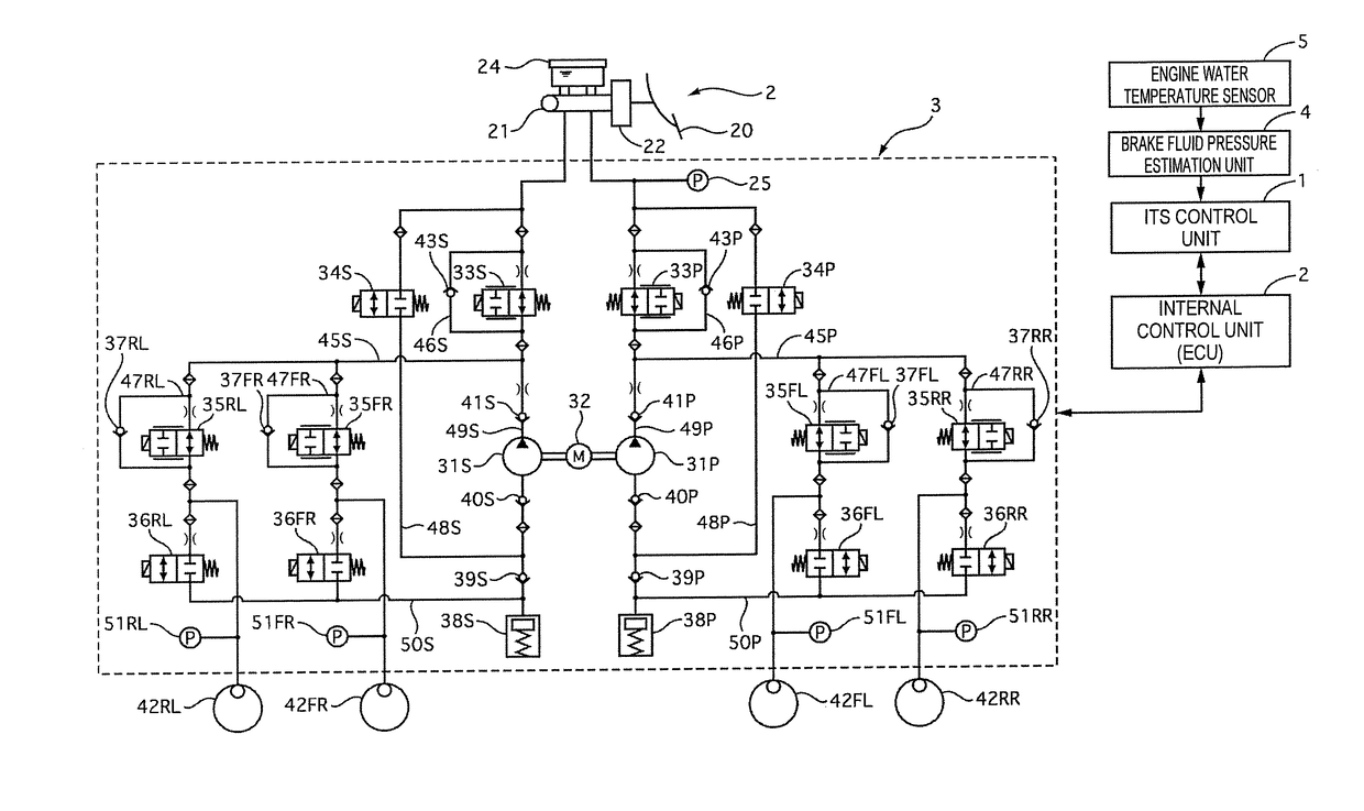
[0023]FIG. 1 shows a hydraulic pressure circuit located in a hydraulic pressure control unit 3. The hydraulic pressure control unit 3 includes an internal control unit 2. The internal control unit 2 controls a motor 32 and valves on the basis of a variety of information. The internal control unit 2 is connected to an ITS control unit 1 through a controller area network (CAN). The ITS control unit 1 calculates a target hydraulic pressure of each wheel cylinder 42 on the basis of Automatic Emergency Braking (AEB: automatic emergency break), Electronic Stability Control (ESC: skidding prevention device), Adaptive Cruise Control (ACC: automatic adaptive cruise control system), Lane Departure Prevention (LDP: lane departure prevention assist system), etc. The ITS control unit 1 receives an estimate value of brake fluid temperature which is input from a brake flui...

embodiment 2

[0059]Embodiment 2 differs from Embodiment 1 in method of controlling the motor 32. Constituent elements identical to those of Embodiment 1 will be provided with identical reference marks, and descriptions thereof will be omitted. Embodiment 2 implements control for eliminating backlash between the brake pad and the brake disc at the start of braking.

[Hydraulic Pressure Control]

[0060]FIG. 4 is a time chart showing a hydraulic pressure command value calculated by the ITS control unit 1 during ACC or LDP, motor rotational frequency, control currents of the gate in valves 34, and control currents of the gate out valves 33.

[0061]At time t21, the hydraulic pressure command value starts increasing. In response to the increase of the hydraulic pressure command value, the gate in valves 34 are opened. The motor 32 then rotates, and the plunger pumps 31 are activated. The rotational frequency of the motor 32 is set higher than during the first and the second pressure increase of Embodiment 1...

embodiment 3

[0076]Embodiment 3 differs from Embodiment 1 in method of controlling the motor 32. Constituent elements identical to those of Embodiment 1 will be provided with identical reference marks, and descriptions thereof will be omitted. Embodiment 3 changes the setting of the rotational frequency of the motor 32 in accordance with brake fluid temperature.

[Hydraulic Pressure Control]

[0077]FIG. 5 is a time chart showing a hydraulic pressure command value calculated by the ITS control unit 1 during ACC or LDP, motor rotational frequency, control currents of the gate in valves 34, and control currents of the gate out valves 33.

[0078]At time t31, the hydraulic pressure command value starts increasing. In response to the increase of the hydraulic pressure command value, the gate in valves 34 are opened. The motor 32 then rotates, and the plunger pumps 31 are activated. The rotational frequency of the motor 32 is set so that the hydraulic pressure according to the hydraulic pressure command valu...


PUM


Abstract

a brake control system adapted to prevent or reduce noise is provided.A brake control system switches a pressure increase mode between first pressure increase that closes a differential pressure valve placed between a master cylinder and a wheel cylinder and activates a pump to increase wheel cylinder hydraulic pressure and second pressure increase that allows brake fluid to leak through the differential pressure valve and activates the pump to increase the wheel cylinder hydraulic pressure, according to the state of a vehicle.

Description

TECHNICAL FIELD[0001]The present invention relates to a brake control system.BACKGOUND ART[0002]The technology described in Patent Document 1 below has been disclosed as a technology of this kind. Patent Document 1 discloses the technology that employs a pulse-pressure decreasing unit to reduce the noise made by pulse pressure of the brake fluid that is discharged from a pump.CITATION LISTPatent Document[0003]Patent Document 1: Japanese Unexamined Patent Application Publication (Kokai) No. 2005-096520SUMMARY OF INVENTION[0004]Patent Document 1 employs a pulse-pressure decreasing unit that is separately provided, which might increase costs.[0005]The present invention has been made in light of the foregoing problem. An object of the invention is to provide a brake control system capable of controlling noise without adding another unit.[0006]To accomplish the object mentioned above, a first embodiment of the invention switches a pressure increase mode between first pressure increase wh...

Claims


Application Information

Patent Timeline
IPC IPC(8): B60T8/40B60T8/34
CPCB60T8/404B60T8/341B60T8/4022B60Y2306/09B60T2201/02B60T2201/08B60T2201/12B60T8/48B60T8/3655B60T8/4059B60T8/4872B60T8/5018
Inventor OHTSU, NOBUYUKI
Owner HITACHI AUTOMOTIVE SYST LTD
Why Eureka
Try Eureka