Method for removing iron sulfide scale

Inactive Publication Date: 2017-07-13
KING FAHD UNIVERSITY OF PETROLEUM AND MINERALS
View PDF0 Cites 9 Cited by
  • Summary
  • Abstract
  • Description
  • Claims
  • Application Information

AI Technical Summary

Benefits of technology

[0025]In one or more embodiments, the method further comprises treating the composition containing the dissolved iron sulfide scale with an effective amount of at least one iron reducing agent to reduce Fe3+ to Fe2+, acidifying the composition containing the dissolved iron sulfide scale to form a precipitant of DTPA and/or a precipitant of at least one insoluble iron salt, isolating the precipitated DTPA and/or the precipitated at least one insoluble iron salt from the composition, selectively dissolving the precipitated DTPA in another composition, and/or removing the precipitated at least on

Problems solved by technology

The corrosive nature of H2S causes the accumulation of particulate iron sulfide.
Such deposits present a significant problem because the deposits hinder accurate determinations of pipeline structural integrity and the pipelines must be cleaned physically.
The buildup of iron sulfide scale deposits over time can lead to a range of operational problems at a wellbore's completion and production stages, from inhibiting the performance of downhole tools to inducing formation damage and plugging of associated equipment, whether such equipment is located downhole or at the surface of the wellbore.
The iron sulfide scale deposits may block flow of the natural resources by clogging perforations or forming a thick lining in the production tubing.
The iron sulfide scale deposits can also coat and damage wellbore equipment, such as heating turbines, heat exchangers, safety valves, casings, production tubing, mandrels, pipes, separators, pumps, etc.
If the iron sulfide scale deposits are not removed, the wellbore production capacity can diminish drastically, and in some cases the iron sulfide scale deposits can cause the wellbore production to be shut down for a period of time.
Additionally, the iron sulfide scale deposits can lead to increased corrosion rates within

Method used


Image

  • Method for removing iron sulfide scale
  • Method for removing iron sulfide scale
  • Method for removing iron sulfide scale

Examples


example 1

Preparation of the Iron Sulfide Scale Removing Composition and Determination of the Solubility of Pyrite (FeS2) Scale Particles in the Removing Composition

[0091]The iron sulfide scale removing composition was prepared by dissolving the chelating agent diethylene triamine pentaacetic acid (DTPA) and the converting agent potassium carbonate (K2CO3) in water to reach the final concentration of 0.5 M and 0.43 M, respectively, and adjusting the pH of the solution to 12-13 with a concentrated potassium hydroxide solution.

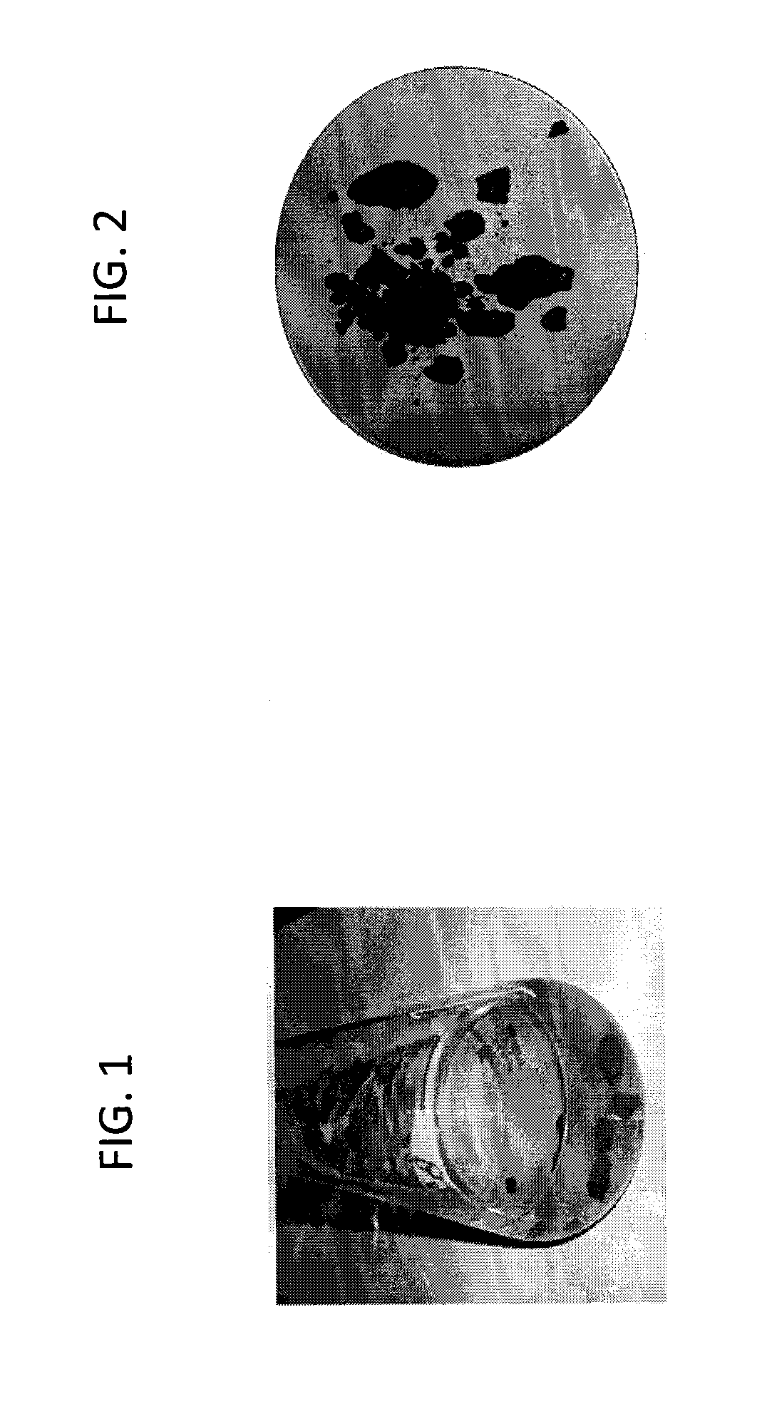
[0092]Pyrite (FeS2) scale particles collected from the field were then mixed with and let soak in the above iron sulfide scale removing composition in various ratios (grams of the pyrite scale particles to milliliters of the removing composition) for 24, 48, or 72 hours at 70° C. to determine the solubility of the pyrite scale particles and the dissolution / removal efficiency of the removing composition under each condition.

[0093]FIG. 1 shows the mixture of the pyrite scal...

example 2

Determination and Comparison of the Pyrite Scale Removal Efficiencies of the Removing Composition (DTPA / Converter), DTPA, a Low pH BDCA Solution, and 20 wt % HCl

[0096]The pyrite scale removal efficiencies of 0.5 M DTPA (pH 12-13), a low pH bio-degradable chelating agent (BDCA) solution comprising 0.5M GLDA at a pH of 3-4, and 20 wt % HCl were likewise determined in parallel with the removing composition (DTPA / Converter) following a 48-hour soaking treatment at 70° C., with the results presented in FIG. 7. The removing composition (DTPA / Converter) exhibited the highest pyrite scale removal efficiency of 85%, followed by, in descending order, 0.5 M DTPA with a 45% removal efficiency, the low pH BDCA solution with a 35% removal efficiency, and 20 wt % HCl with a 20% removal efficiency.


PUM


Abstract

A method of removing an iron sulfide scale from a surface in fluid communication with a wellbore and/or subterranean formation comprising contacting the iron sulfide scale on the surface with a composition to dissolve the iron sulfide scale in the composition. The composition comprises (a) at least one chelating agent selected from the group consisting of DTPA, EDTA, HEDTA, GLDA, CDTA, and MGDA, and salts thereof, and (b) at least one converting agent selected from the group consisting of potassium carbonate (K2CO3), potassium formate (HCOOK), potassium hydroxide (KOH), potassium chloride (KCl), cesium formate (HCOOCs), and cesium chloride (CsCl). In the composition, the weight ratio of (a):(b) lies in the range 7-60:2-20.

Description

BACKGROUND OF THE INVENTION[0001]Technical Field[0002]The present disclosure relates to methods of removing iron sulfide scale deposits from surfaces in fluid communication with a wellbore and / or subterranean formation, and more particularly to methods for removing such deposits with a composition comprising at least one chelating agent and at least one converting agent.[0003]Description of the Related Art[0004]The “background” description provided herein is for the purpose of generally presenting the context of the disclosure. Work of the presently named inventors, to the extent it is described in this background section, as well as aspects of the description which may not otherwise qualify as prior art at the time of filing, is neither expressly nor impliedly admitted as prior art against the present invention.[0005]During the production stage of a wellbore, fluids (e.g., gas, oil, steam, hot water, etc.)[0006]are generally produced from the wellbore, and scale can develop in the ...

Claims


Application Information

Patent Timeline
IPC IPC(8): C09K8/532E21B37/06
CPCE21B37/06C09K8/532C09K8/528
Inventor MAHMOUD, MOHAMED AHMED NASRELDINBA GERI, BADR SALEMHUSSEIN, LBNELWALEED A.
Owner KING FAHD UNIVERSITY OF PETROLEUM AND MINERALS
Why Eureka
Try Eureka