Method and device for deodorization and purification of exhaust gas or flue gas

a technology of exhaust gas and purification method, which is applied in the direction of machines/engines, lighting and heating apparatus, separation processes, etc., can solve the problems of increasing the cost of replacement of agents, requiring a lot of space, and not being able to provide sufficient deodorization, etc., and achieves easy electrolysis, high current density, and high chlorine concentration.

Inactive Publication Date: 2003-09-04
OMEGA CO LTD
View PDF5 Cites 90 Cited by
  • Summary
  • Abstract
  • Description
  • Claims
  • Application Information

AI Technical Summary

Benefits of technology

0029] With these factories and plants, exhaust gas is normally released into the atmosphere through a benthos scrubber or the like, and with this application it is possible to remove organic solvents contained within exhaust gas through oxidation and decomposition by simply subjecting this benthos scrubber water to electrolytic processing. These organic solvents, are materials that can be easily electrolyzed, and it is preferable to process these solvents by electrolysis at a high current density and with a high available chlorine concentration.
0030] The present invention is an electrolytic device having an anode that is a conductive metal with conductive ceramics or a vapor deposited or thermal spray film of conductive ceramics, or alternatively a vapor deposited or thermal spray film of diamond with additional conductivity, formed on a metallic surface of the conductive metal, and a cathode that is a co

Problems solved by technology

These are all large scale installations, and require a lot of space.
Also, deodorization and purification of exhaust gas or flue gas has a problem that depending on the composition of the exhaust or flue gas it is not possible to provide sufficient deodorization and purification unless a number of the above described methods are combined.
If performance is lowered with degradation of the agents used, there is also a problem of increased costs due to replacement of the agents.
Tobacco smoke is also harmful to other people in the room besides the smoker.
Moreover, even when air cleaners which have begun to become widespread are used to deodorize and remove dust, it has become clear that there is a problem that it is not possible to remove and purify the bulk of those components that are considered most likely to be harmful in tobacco smoke, such as carbon monoxide and nicotine (Japan Electric Industry Association: Japan anti-smoking league, Dr.
However, bad odor, smoke and harmful material in exhaust gas or flue gas, which is the subject at this time, cannot be dealt with sufficiently with methods proposed to date when there is a large amount of a heterogeneous component in high concentration.
It is also very easy for harmful trihalomethane to be generated if some water soluble organic matter comes into contac

Method used


Image

  • Method and device for deodorization and purification of exhaust gas or flue gas
  • Method and device for deodorization and purification of exhaust gas or flue gas
  • Method and device for deodorization and purification of exhaust gas or flue gas

Examples


example 2

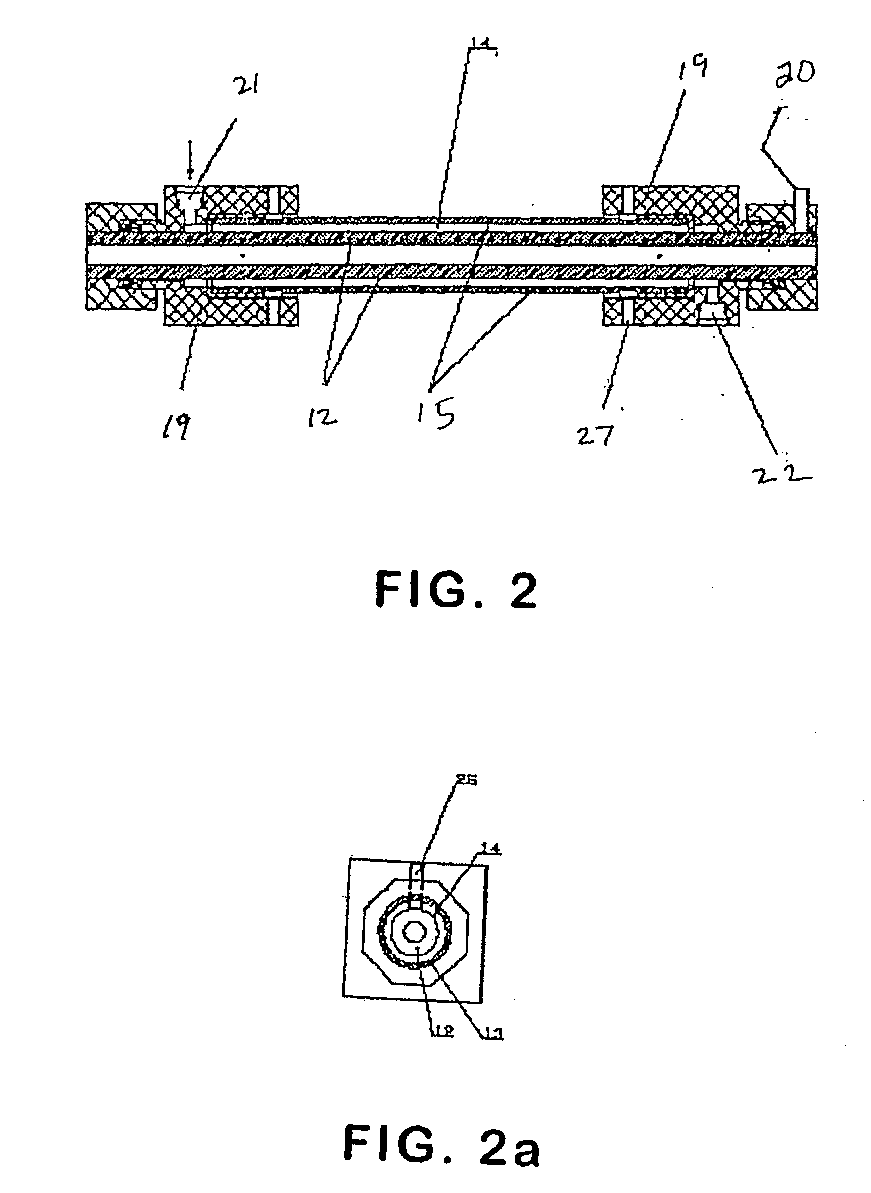
[0042] Next, a description will be given of the present invention for absorbing bad odor in circulating water by driving the electrolytic reactor 3 at the same time as removing bad odor in discharged water. An electrolytic reactor is shown in FIG. 2 and 2a and has an anode 12 that is a nickel ferrite tube with an outer diameter of 28 mm, a thickness of 8 mm and a length of 280 mm. An anode cathode distance is 4 mm, and a cathode 13 outside the anode tube 12 is an SUS316L pipe 15 having an outer diameter of 42.7 mm, a thickness of 3 mm, an electrode length of 280 mm, overall length 325.1 mm. A circulating water inlet 21 for introducing water solution containing halogen ions into an inter electrode reaction section 14 is provided in an electrode fixing section 19 formed from a nonconductive material at the base of the anode and electrode, and electrolytic sterilization and purification water outlet 22 is formed at an uppermost part of the electrode fixing section 19.

[0043] Electrolysi...

example 3

[0047] This example is a research report commissioned by the Okayama Prefectural Research Center, Food Industry Study Group (Dr. Satoshi Fukuzaki).

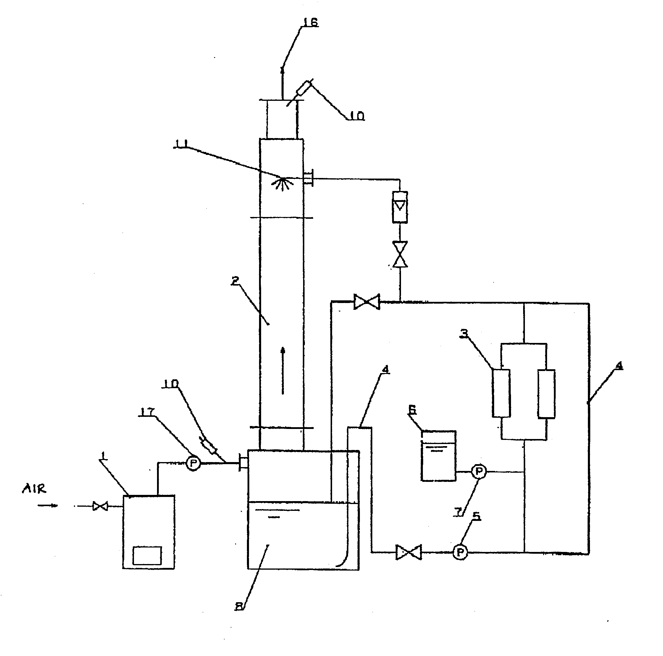
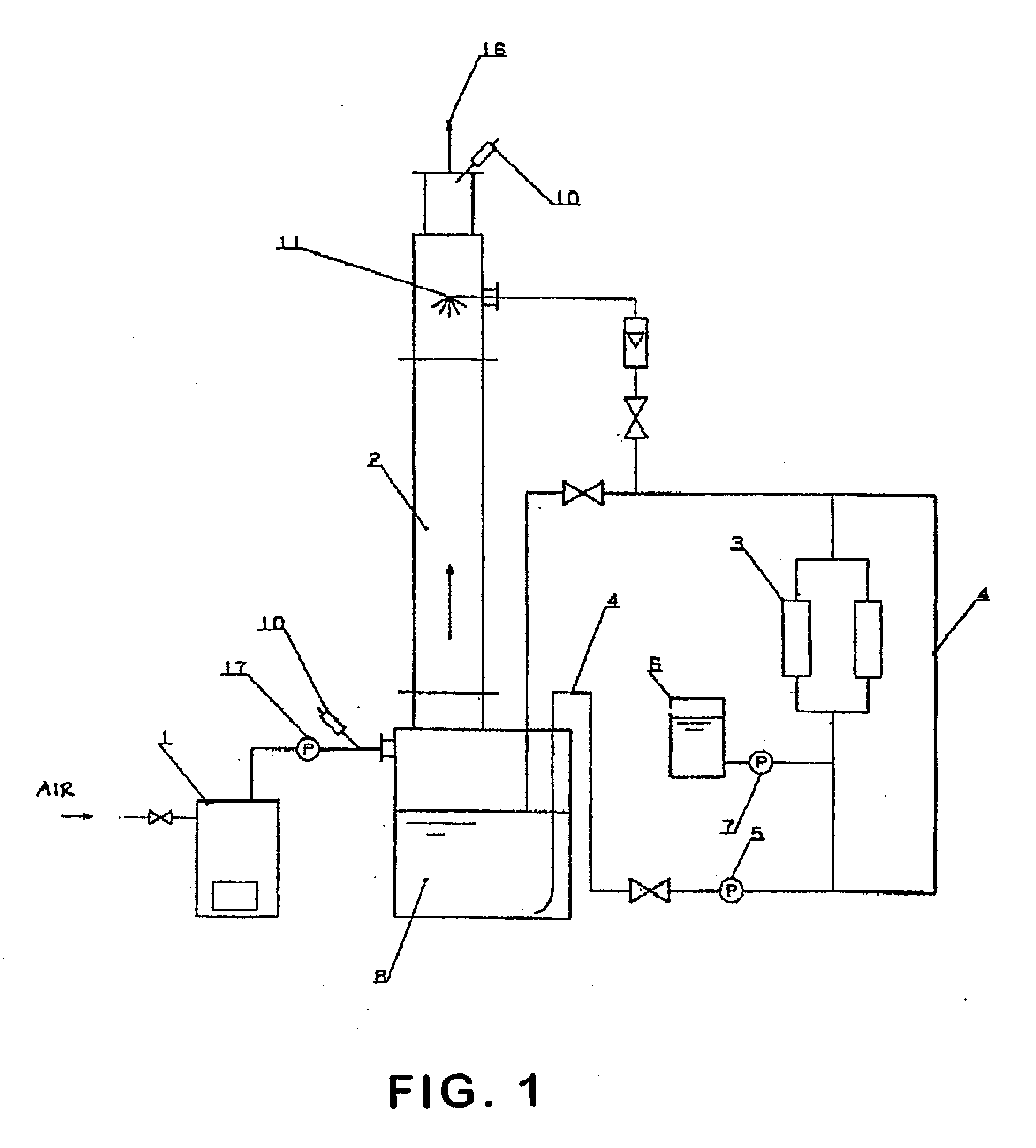
[0048] FIG. 3 is a flow drawing of a test using a shower ring type deodorizer of 501 capacity. Odorous substance from a bad smelling gas or harmful gas generating section 1 or a bad smelling gas container (such as a gas cylinder) 18 is extracted by a blower 17 and fed to the absorption means (deodorizing tower) 2 (volume 50 liters in this example). Bottled hydrogen sulfide was used as a bad smelling component produced by protein hydrolysis, and methyl thioalcohol was used as a bad smelling reference gas.

[0049] Testing was carried out under conditions of supply amount of bad smelling gas to a deodorizer in shower water of the electrolytic circulating water solution receiving tank 8 33L / min and shower jet amount 3.7L / min. As the shower water mains water, NaCl (0.1%) electrolytic water solution adjusted from mains water and NaNO.sub.3 (0.1%)...

example 4

[0053] This example has the showering type deodorizer shown FIG. 3 applied to an amino acid manufacturing plant, and deodorization testing was carried out using alkaline sodium chloride electrolytic water solution (available chlorine concentration 110 mg / L). (1) Flow rate of deodorization hydrogen sulfide gas of hydrogen sulfide produced from anaerobic waste water treatment tank (methane fermentation tank): 65L / min (retention time: 0.8 min)

[0054] showering water amount: 3.7L / min

[0055] available chlorine concentration (HOCl) electrolytic water solution: 110 mg / L

[0056] For the purpose of comparison, testing was also carried out with a currently often used method (ozone gas+water shower). Results are shown in Table 2.

2TABLE 2 Available chlorine concentration (HOCl) electrolytic water solution: 110 mg / L pH 9.5 Before Bad smelling deodorization After deodorization component (mg / l) (mg / l) Removal rate Ozone gas (480 450 300 33.3 mg / l) + water shower Electrolytic water 450 16 96.4 solution...


PUM

PropertyMeasurementUnit
Acidityaaaaaaaaaa
Fractionaaaaaaaaaa
Fractionaaaaaaaaaa

Abstract

A method and device for removing, deodorizing and purifying odor, smoke and harmful substances from exhaust gas or flue gas employs a water solution containing hypohalogen acid such as hypochlorous acid soda, an alkaline electrolyte such as potassium hydroxide or sodium hydroxide and a saline electrolyte such as sodium chloride, potassium chloride, sodium bromide or potassium bromide which is electrolyzed to produce an electrolytic water solution which is fed to a deodorizing tower and brought into contact with exhaust gas or flue gas to remove odor, smoke and harmful substances in the exhaust gas or flue gas.

Description

[0001] 1. Field of the Invention[0002] The present invention relates to a method and a device for efficiently removing odor, smoke and harmful material from exhaust gas or flue gas emitted from, chemical devices, waste water treatment equipment, processes such as drying, incineration, and treatment of waste and human waste, cooking facilities such as restaurants, hospitals, elderly care facilities, offices, homes and entertainment centers such as game arcades, and for carrying out sterilization.[0003] 2. Description of the Related Art[0004] Conventionally, odor, smoke and harmful material in exhaust gas emitted from chemical devices, waste water treatment equipment, processes such as drying, incineration, and treatment of waste and human waste, and cooking facilities such as restaurants have been absorbed using chemical agents such as a alkali or acidic solution as an absorbent, and then processed by method of absorbing with a packed tower, spray tower, wetted wall tower or stepped ...

Claims


Application Information

Patent Timeline
IPC IPC(8): A61L9/01F01N3/02A61L9/14A61L9/16B01D47/06B01D53/14B01D53/18B01D53/38B01D53/44B01D53/50B01D53/56B01D53/62B01D53/72B01D53/77C02F1/46C02F1/467F01N3/04F01N3/08F23J15/04
CPCB01D47/06C02F1/4674B01D53/1493
Inventor NAKAMURA, SHINICHIFUKUZUKA, KUNIHIKONAKAZAWA, JINGO
Owner OMEGA CO LTD
Why Eureka
Try Eureka