Ventilation fan and drying system and method of using the same

a technology of ventilation fan and drying system, which is applied in ventilation system, lighting and heating apparatus, heating types, etc., can solve the problems of significant performance drop, hamper the ability of the evacuation fan to exhaust air from the enclosure, etc., and achieve the effect of reducing the negative pressure buildup within the evacuation, and reducing the risk of damag

Active Publication Date: 2017-07-20
WILLIAMS ARCH +1
View PDF9 Cites 8 Cited by
  • Summary
  • Abstract
  • Description
  • Claims
  • Application Information

AI Technical Summary

Benefits of technology

[0004]When conventional evacuation fans are put to actual use, there is a significant drop in performance compared to the maximum potential for a given fan size, motor speed and evacuation area. When installed in enclosures, such as bathrooms, conventional evacuation fans have a tendency to create a negative pressure within the enclosed space, hampering the ability of the evacuation fan to exhaust air from the enclosure. Therefore one aspect of the present disclosure is to provide a ventilation system that mitigates the negative pressure buildup within the evacuated space, allowing an evacuation system to perform much more efficiently with respect to air removal. This reduces the amount of time the system needs to operate, which may also provide energy savings.
[0005]Another aspect of the disclosed ventilation system is that the system can improve drying time of the enclosed space by being able to not only function as an air evacuation system but also act as an air recirculation system. By combining the ability to evacuate and recirculate air, the ventilation system disclosed herein improves the drying time of an enclosed space, helping to improve safety by limiting the presence of wet, slippery surfaces, and helping to improve health and cleanliness by reducing the factors that lead to growth of bacteria, mold, mildew, fungus and other allergens.

Problems solved by technology

When conventional evacuation fans are put to actual use, there is a significant drop in performance compared to the maximum potential for a given fan size, motor speed and evacuation area.
When installed in enclosures, such as bathrooms, conventional evacuation fans have a tendency to create a negative pressure within the enclosed space, hampering the ability of the evacuation fan to exhaust air from the enclosure.

Method used


Image

  • Ventilation fan and drying system and method of using the same
  • Ventilation fan and drying system and method of using the same
  • Ventilation fan and drying system and method of using the same

Examples


Embodiment Construction

[0015]Exemplary embodiments are described below and illustrated in the accompanying drawings, in which like numerals refer to like parts throughout the several views. The embodiments described provide examples and should not be interpreted as limiting the scope of the inventions.

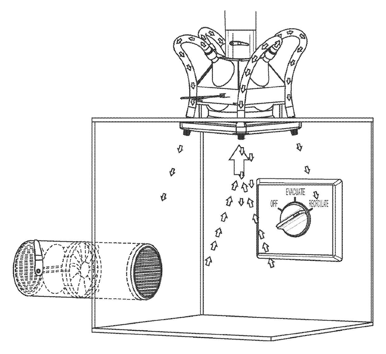
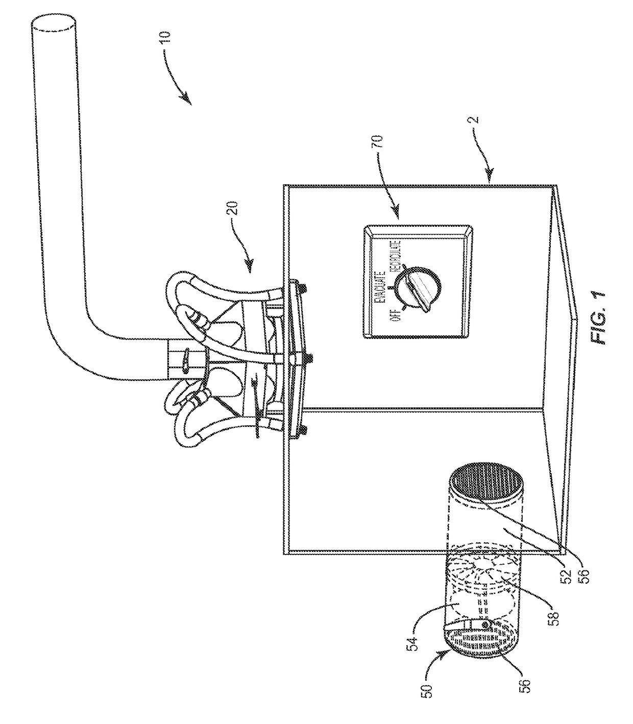
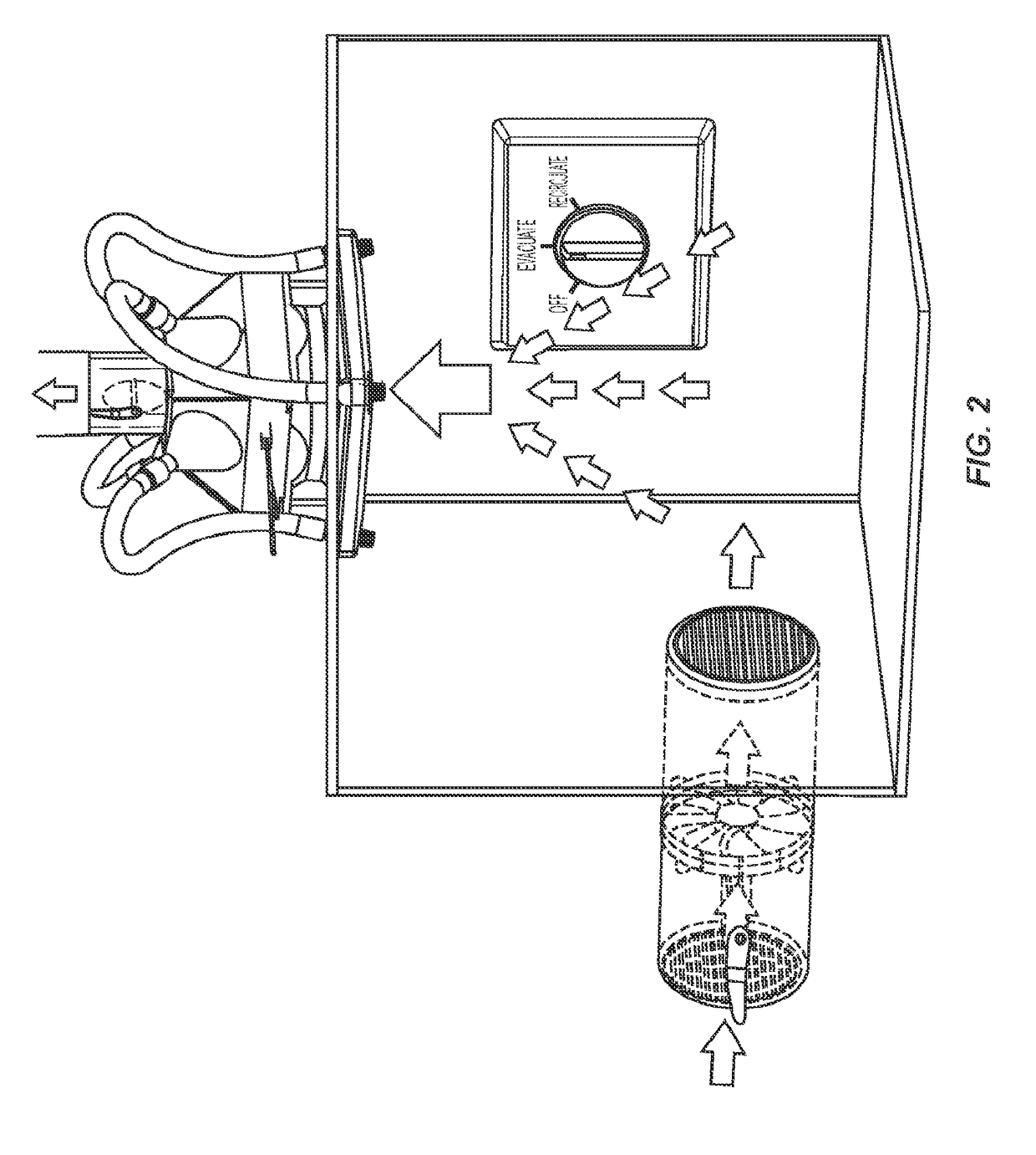
[0016]Turning to the figures, FIG. 1 shows an air circulation and ventilation system 10 in relation to a generally enclosed space or enclosure 2 such as a residential bathroom. A bathroom is a preferred example of an enclosure 2 for which the ventilation system 10 may be employed because, when in use by a person, the door or doors for entrance and egress of the person are generally maintained in a closed position, substantially enclosing the room. It is understood that a bathroom with doors closed is not a completely air-tight box, but should still be considered enclosed because of the minimal area for flow of air into and out of the space. A bathroom is a preferred example of an enclosure 2 because of the i...


PUM


Abstract

An air circulation and ventilation system for an enclosure. The system includes a fan assembly subsystem with a housing defining a manifold. The housing has a first intake aperture configured to receive air from within the enclosure, a first outlet aperture configured to emit air from the manifold to outside the enclosure, and a fan configured to draw air in through the first intake aperture. The system includes a pressure equalization subsystem having a port configured to allow additional air into the enclosure. The port includes a damper for selectively opening and closing the port. The system also includes a switching subsystem with a switch operably coupled to the fan and the damper. The switch selects between a first mode where the damper is closed and the fan is off and a second mode where the port damper is open and the fan is on.

Description

FIELD OF INVENTION[0001]The present disclosure relates to ventilation systems providing improvements in evacuation efficiency. In some embodiments the ventilation systems are adapted to improve drying of wet or humid areas such as residential bathrooms.BACKGROUND OF THE INVENTION[0002]Bathrooms are often equipped with evacuation fans. When turning on these fans, they attempt to pull air from the bathroom and exhaust air from the bathroom out to the exterior of the building. These evacuation fans are designed to remove foul air from the room. Foul air can be noxious air or may be humid air or steam created during a hot shower.[0003]Evacuation fans presently on the market are classified based upon factors such as airflow rate / volume, fan / motor size, noise, integrated lighting options, and integrated heating options. The present disclosure provides a ventilation system that improves upon the function of these known fans.SUMMARY[0004]When conventional evacuation fans are put to actual u...

Claims


Application Information

Patent Timeline
Patent Type & Authority Applications(United States)
IPC IPC(8): F24F11/04F24F7/06F24F11/00F26B5/00F26B21/12
CPCF24F11/04F26B5/00F24F2007/001F24F11/0015F24F7/06F26B21/12F24F11/0001F24F11/72F24F11/74F24F2110/20F24F11/30F24F11/755
Inventor WILLIAMS, ARCHDUNLAP, BENJAMIN C
Owner WILLIAMS ARCH
Why Eureka
Try Eureka