Vehicle electronic control device and motor drive device

a technology of electronic control device and motor drive, which is applied in the direction of coupling device connection, electrical apparatus casing/cabinet/drawer, display/control unit casing, etc., can solve the problems of short circuit, electronic control device not working, water drop, etc., to simplify waterproof structure, enhance waterproof function, cost reduction

Active Publication Date: 2017-07-20
MITSUBISHI ELECTRIC CORP
View PDF11 Cites 7 Cited by
  • Summary
  • Abstract
  • Description
  • Claims
  • Application Information

AI Technical Summary

Benefits of technology

[0012]The present invention can achieve a vehicle electronic control device and a motor drive device that have an enhanced waterproof function around a connector and have a further simplified waterproof structure, thereby achieving cost reduction and size reduction.

Problems solved by technology

However, even in the case of using a waterproof connector, it is necessary to also consider that a very small gap arises between a housing and a terminal provided in the housing, and then, due to temperature change by heat generation and cooling of an electronic device, water drop is absorbed.
In particular, if water drop enters the electronic control device, short-circuit occurs because of small-sized components.
As a result, the electronic control device does not function, and further, travelling of the vehicle might be influenced.

Method used


Image

  • Vehicle electronic control device and motor drive device
  • Vehicle electronic control device and motor drive device
  • Vehicle electronic control device and motor drive device

Examples


embodiment 1

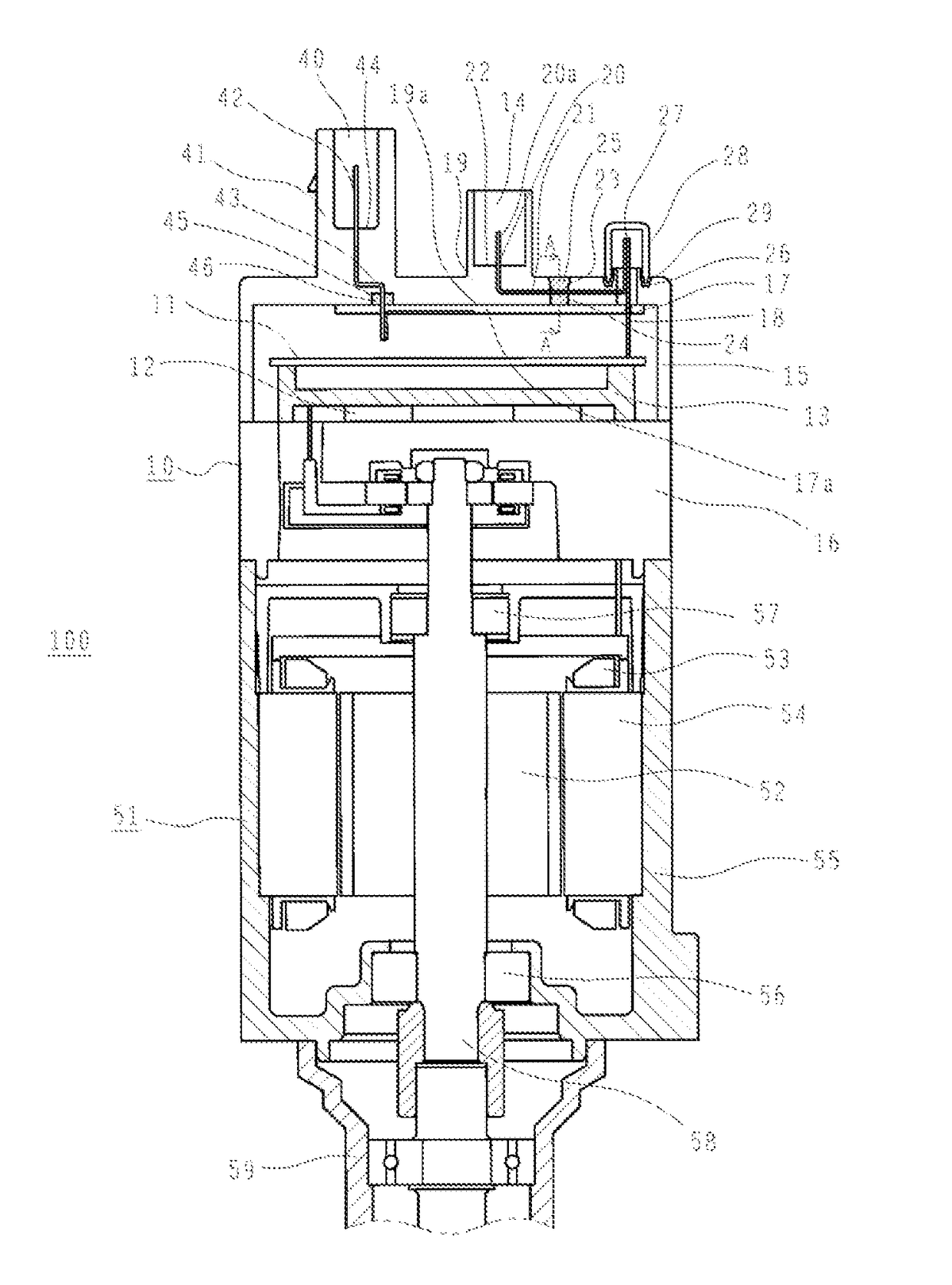
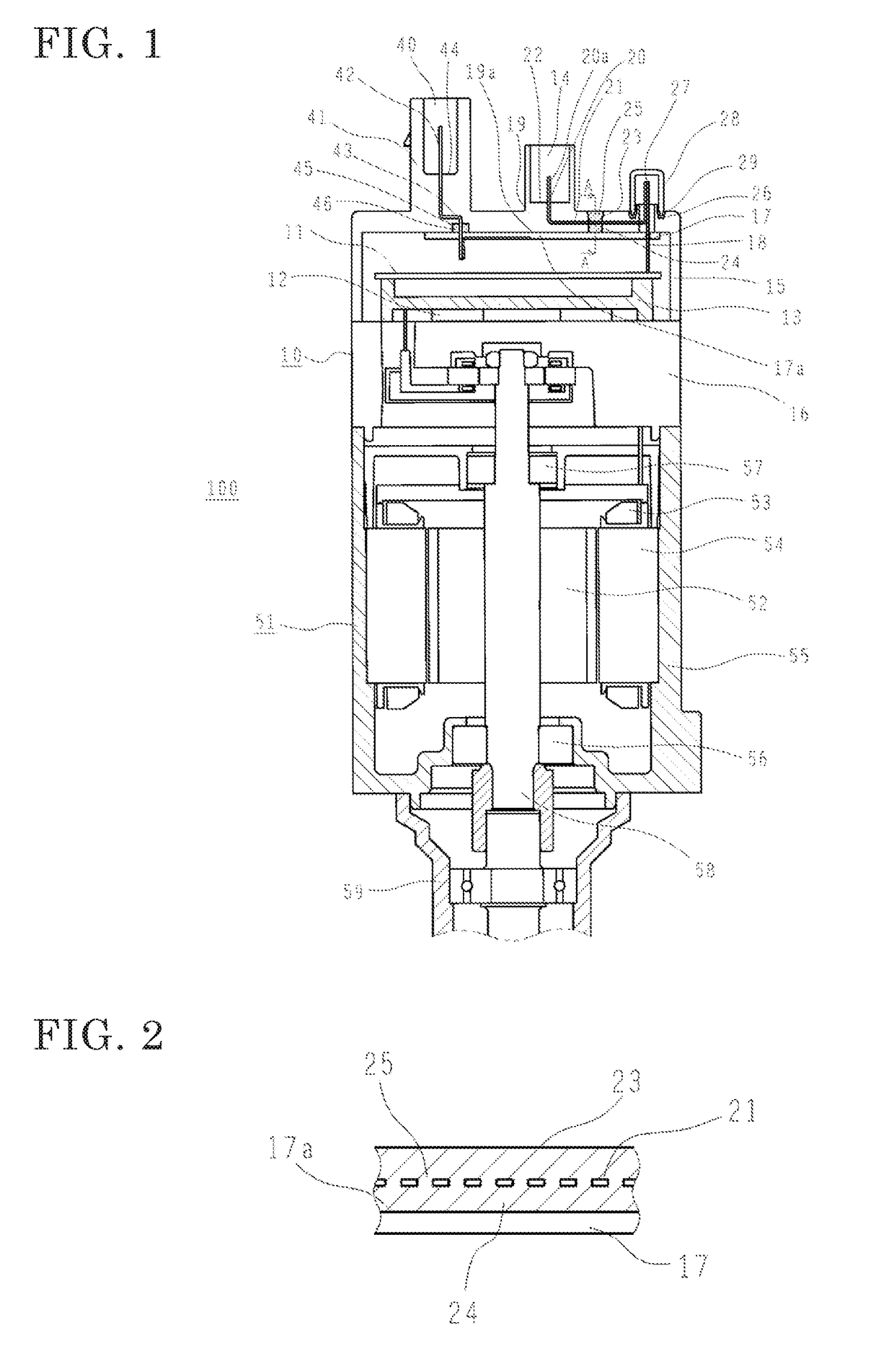
[0024]Hereinafter, embodiment 1 of the present invention will be described with reference to the drawings. FIG. 1 and FIG. 2 are a sectional configuration diagram and an A-A sectional view showing a motor drive device having a vehicle electronic control device according to embodiment 1 of the present invention.

[0025]In FIG. 1 and FIG. 2, the motor drive device 100 is composed of an electric motor 51 and a vehicle electronic control device 10 which is integrally attached to an end in the axial direction of the electric motor 51 and which performs power feeding to the electric motor 51 and drive control for the electric motor 51.

[0026]The electric motor 51 is a three-phase brushless motor, and includes: a rotor 52; a stator 54 having armature windings 53 for U phase, V phase, and W phase; a motor frame 55 covering the outer circumference of the stator 54; an output-side bearing 56 coaxially fixed to the motor frame 55 and rotatably supporting the rotor 52; an anti-output side bearing ...

embodiment 2

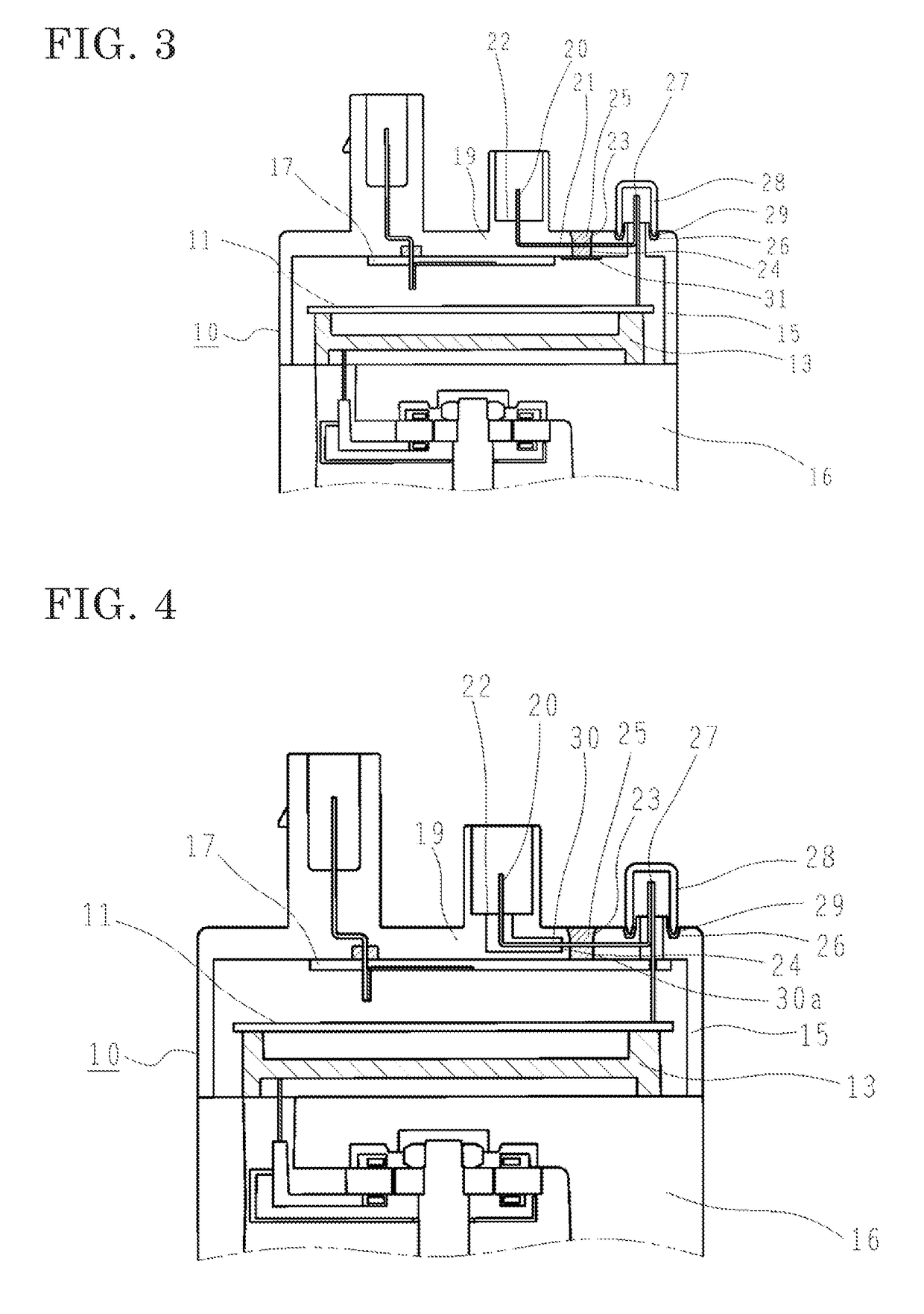
[0038]FIG. 3 is a partial sectional configuration diagram showing a vehicle electronic control device according to embodiment 2 of the present invention.

[0039]In embodiment 1, as for the groove portion 24, the upper surface 17a of the case frame 17 and the inner surface 19a of the housing portion 19 are fixed in close contact with each other, and the groove portion 24 with a bottom is formed by the exposure portion 23 and the upper surface 17a of the case frame 17. On the other hand, in the present embodiment 2, instead of the case frame 17, a plate 31 is attached at the upper surface 17a of the case frame 17, thereby forming the groove portion 24 with a bottom.

[0040]As the plate 31, an adhesive tape may be used.

[0041]Even such a configuration can provide the same effect as in embodiment 1.

embodiment 3

[0042]FIG. 4 is a partial sectional configuration diagram showing a vehicle electronic control device according to embodiment. 3 of the present invention.

[0043]In the above embodiments 1 and 2, the intermediate path portion 21 of the terminal portion 20 is a single component made of a metallic conductor. On the other hand, in the present embodiment 3, as the terminal portion 20, a pre-mold type is used. The intermediate path portion 21 at a part other than the exposure portion 23 is partially covered with a pre-mold resin 30 formed separately from the housing portion 19, and an end 30a on the exposure portion 23 side of the pre-mold resin 30 is positioned away from the exposure portion 23 toward the seat face portion 22 side.

[0044]Such a configuration allows the same effect as in the embodiments 1 and 2 to be obtained even in the case of using the terminal portion 20 of a pre-mold type.


PUM


Abstract

In this vehicle electronic control device, a control board having an electronic component mounted thereon is housed inside a case and a connector portion for connecting the control board to the outside is formed integrally with the case. The connector portion is formed by a housing portion covering the control board, and a terminal portion integrally embedded in the housing portion. The terminal portion has: a terminal for external connection, protruding from the housing portion; and an intermediate path portion extending from the terminal and connected to the control board. An exposure portion which allows the intermediate path portion to be exposed over the entire periphery thereof is formed in a part of the housing portion. An interface sealing member for sealing the interface between the housing portion and the intermediate path portion is provided in the exposure portion.

Description

TECHNICAL FIELD[0001]The present invention relates to a vehicle electronic control device and a motor drive device, and in particular, to a waterproof structure around a connector for transferring power, a signal, and the like for these devices.BACKGROUND ART[0002]Some of conventional waterproof structures around a connector of a vehicle electronic control device use a waterproof connector to address waterproofness.[0003]However, even in the case of using a waterproof connector, it is necessary to also consider that a very small gap arises between a housing and a terminal provided in the housing, and then, due to temperature change by heat generation and cooling of an electronic device, water drop is absorbed.[0004]In particular, if water drop enters the electronic control device, short-circuit occurs because of small-sized components. As a result, the electronic control device does not function, and further, travelling of the vehicle might be influenced. Accordingly, reliably ensur...

Claims


Application Information

Patent Timeline
Patent Type & Authority Applications(United States)
IPC IPC(8): H02K11/00H01R13/52B60R16/03H05K5/00H05K5/02H05K5/06H01R13/405H02K11/33
CPCH02K11/0094H01R13/405H01R13/5219B60R16/03H05K5/0017H05K5/0247H05K5/064H02K11/33H01R13/52H02K5/225
Inventor USHIO, KOHEIASAO, YOSHIHITOMORI, AKIHIKO
Owner MITSUBISHI ELECTRIC CORP
Why Eureka
Try Eureka