Method for operating a tongs system for use on a rig and corresponding tongs system, computer program for implementing the method and rig comprising a tongs system

a tongs system and rig technology, applied in the direction of torque/twisting force measurement, earth drilling and mining, drilling accessories, etc., can solve the problem of not being able to maintain a defined or definable tightening torque and achieve the effect of less contamination and damag

Inactive Publication Date: 2017-07-27
BENTEC DRILLING & OILFIELD SYST
View PDF3 Cites 16 Cited by
  • Summary
  • Abstract
  • Description
  • Claims
  • Application Information

AI Technical Summary

Benefits of technology

[0009]The advantage of the concept proposed here is especially that the threaded sections of the two drill pipe elements are connected with a defined tightening torque and that it is ensured that, on the one hand, the tightening torque is reliably achieved, i.e. an associated strength of the threaded joint is provided, and that, on the other hand, the tightening torque is also not exceeded or at least not significantly exceeded, with the result that there is no unnecessary wear of the threaded sections of the two drill pipe elements.
[0013]In another embodiment of the method, the upper tongs are moved at a (high) initial speed at the beginning of the connection of the two drill pipe elements, and the speed at which the upper tongs are moved is reduced, starting from the initial speed, in accordance with a countertorque that builds up during the connection of the two drill pipe elements, in particular being reduced continuously or reduced in stages. This leads to a particularly quick connection of the two drill pipe elements in that the upper tongs are initially moved at the high initial speed, and the speed is reduced only when the threaded joint becomes tight or begins to be tight. In comparison with an otherwise conventional constant speed of movement of the upper tongs relative to the lower tongs, it is possible in this way to significantly reduce the time required to connect two drill pipe elements. In the case of successive installation of a multiplicity of drill pipe elements, the time saving is multiplied to give a quite significant amount, depending on the total length of the resulting drill string. Moreover, reducing the speed in accordance with the countertorque allows particularly accurate achievement of the defined desired tightening torque.
[0015]In another embodiment of the method of the type described here and below, which is provided not only for connecting two drill pipe elements but also for releasing a drill pipe element from a fixed drill pipe element, with reference to a respective position of the upper tongs relative to the lower tongs, said position being detected by the displacement measuring system, the upper tongs are moved into a position in which a maximum torque can be exerted before the beginning of release of the connection of the two drill pipe elements. In this way, the position of the upper tongs relative to the lower tongs, which is detectable by means of the displacement measuring system, is used not only to limit the tightening torque to the desired tightening torque, and reliably to achieve said torque, during the connection of two drill pipe elements but also to optimally position the upper tongs during the release of the threaded joint of two drill pipe elements.
[0017]In one embodiment of the tongs system, the displacement measuring system is associated with a drive unit provided for moving the upper tongs relative to the lower tongs, e.g. a hydraulic cylinder acting as a drive unit. An incremental encoder or the like, for example, may be considered as a displacement measuring system or sensor system in a displacement measuring system of this kind. In principle, as an alternative or in addition, consideration may also be given to assigning the displacement measuring system to the lower tongs or the upper tongs and determining the position, in particular the rotational position, of the upper tongs relative to the lower tongs directly. However, assigning the displacement measuring system to the drive unit is regarded as advantageous because—unlike with assignment of the displacement measuring system to the upper or lower tongs—there is less risk of contamination and damage in this region.

Problems solved by technology

However, maintaining a defined or definable tightening torque is not a simple matter if a torque that can be exerted by means of a drive unit varies during the connection or separation of two drill pipe elements.

Method used


Image

  • Method for operating a tongs system for use on a rig and corresponding tongs system, computer program for implementing the method and rig comprising a tongs system
  • Method for operating a tongs system for use on a rig and corresponding tongs system, computer program for implementing the method and rig comprising a tongs system
  • Method for operating a tongs system for use on a rig and corresponding tongs system, computer program for implementing the method and rig comprising a tongs system

Examples


Embodiment Construction

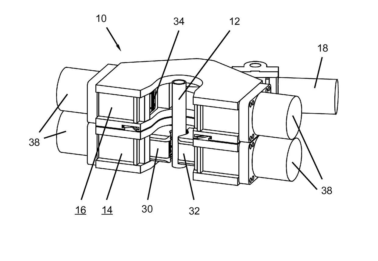
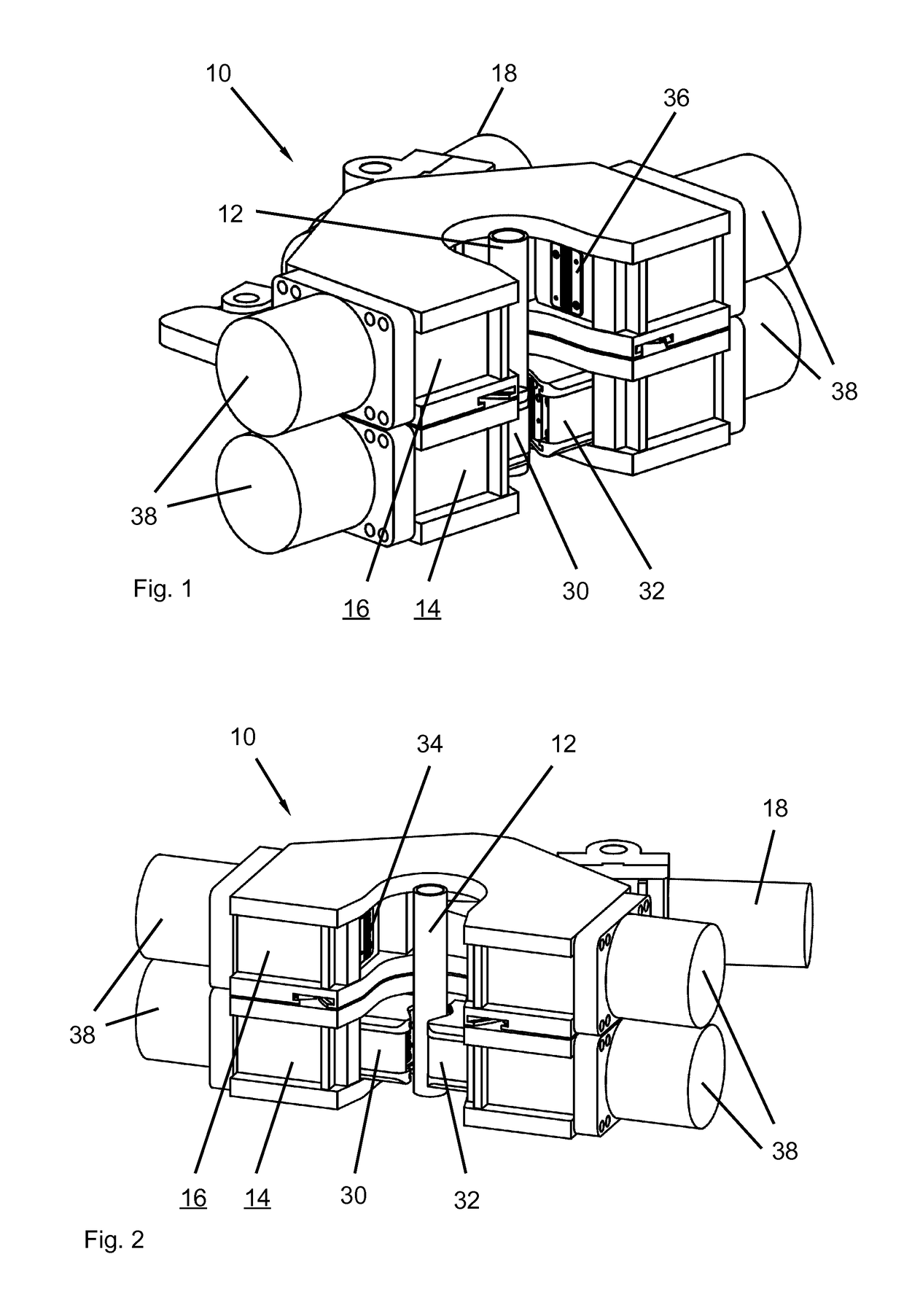
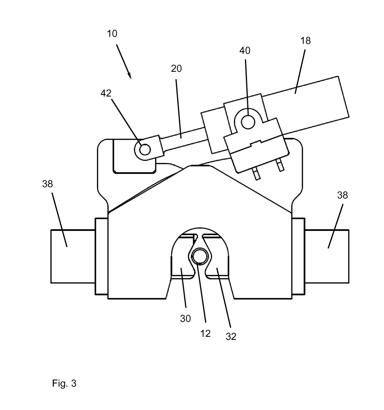
[0025]The illustrations in FIG. 1 and FIG. 2 show isometric views of one embodiment of a specific tongs system 10 from different directions of view, said system being intended for use on the “drill floor” of a rig, known per se but not itself shown, intended for sinking wells in hydrocarbon deposits for crude oil and natural gas exploration or for exploiting geothermal energy. The illustration in FIG. 3 shows the tongs system 10 according to FIG. 1 and FIG. 2 in a plan view.

[0026]The tongs system 10 comprises lower tongs 14 and upper tongs 16. The two tongs 14, 16 can be moved in rotation relative to one another by means of a drive unit 18, here shown as a hydraulic cylinder, allowing a drill pipe element 12 to be released from the drill string or a drill pipe element 12 to be connected to the drill string by means of the tongs system 10. For this purpose, the drive unit 18 is connected non-rotatably to the lower tongs 14, and a piston rod 20 (FIG. 3) that can be moved with the driv...


PUM

PropertyMeasurementUnit
displacement measuring systemaaaaaaaaaa
tightening torqueaaaaaaaaaa
lengthaaaaaaaaaa

Abstract

The invention relates to a method for operating a tongs system (10) designed for assembling a drill string element (12) and an often stationary drill string element (12) or for separating a drill string element (12) from another drill string element (12), said tongs system having lower tongs and upper tongs that can be moved relative to the lower tongs by means of a drive unit (18). A displacement-measuring system (44) detects a position (46) of the upper tongs relative to the lower tongs. A control unit (48) compares an application torque determined as a function of the detected position (46) with a defined or definable desired application torque (54). The assembly of the two drill string elements (12) is terminated when the determined application torque reaches or exceeds the desired application torque (54). The invention also relates to a tongs system (I 0) operating according to said method.

Description

FIELD OF THE INVENTION[0001]The invention relates first and foremost to a method for operating a tongs system for use on a rig for deep wells, e.g. for sinking wells in hydrocarbon deposits for crude oil and natural gas exploration or for exploiting geothermal energy, which system is often also referred to in the specialist jargon as a “floorhand” or “iron roughneck” and can also be designated as an automatic rod clamp. The invention also relates to a tongs system for carrying out the method and for use in accordance with the method.DESCRIPTION OF THE RELATED ART[0002]A tongs system of this kind is described in US 2007 / 068669 A.[0003]A tongs system of the type in question is provided for the purpose of connecting two drill pipe elements or for separating two drill pipe elements, in particular for connecting a drill pipe element to the drill string or for releasing a drill pipe element from the drill string during the installation and removal of the drill pipe. For this purpose, the ...

Claims


Application Information

Patent Timeline
Patent Type & Authority Applications(United States)
IPC IPC(8): E21B19/16G01L5/24E21B17/042
CPCE21B19/166G01L5/24E21B17/042E21B19/163
Inventor AALDERINK, JANREUTER, ANDRECORDES, MALTE
Owner BENTEC DRILLING & OILFIELD SYST
Why Eureka
Try Eureka