
Composite component having a safety edge

a technology of composite components and safety edges, applied in the field of composite components having a safety edge, can solve the problems of /b> being difficult and potentially unsafe to handle, reducing the safety of the component, so as to facilitate bonding and form quickly and easily.

Active Publication Date: 2017-07-27
VESTAS WIND SYST AS
View PDF9 Cites 4 Cited by
  • Summary
  • Abstract
  • Description
  • Claims
  • Application Information

AI Technical Summary

Benefits of technology

The invention provides a way to make a safe edge on a composite wind turbine blade without needing to treat it after it has been made. The edge is made during the fabrication process and is made of resin-free material. This makes it easy to remove any parts of the edge that need to be replaced without having to remove the entire edge. This method is efficient and doesn't require expensive equipment. Overall, this invention helps to make safer wind turbine blades faster and easier.

Problems solved by technology

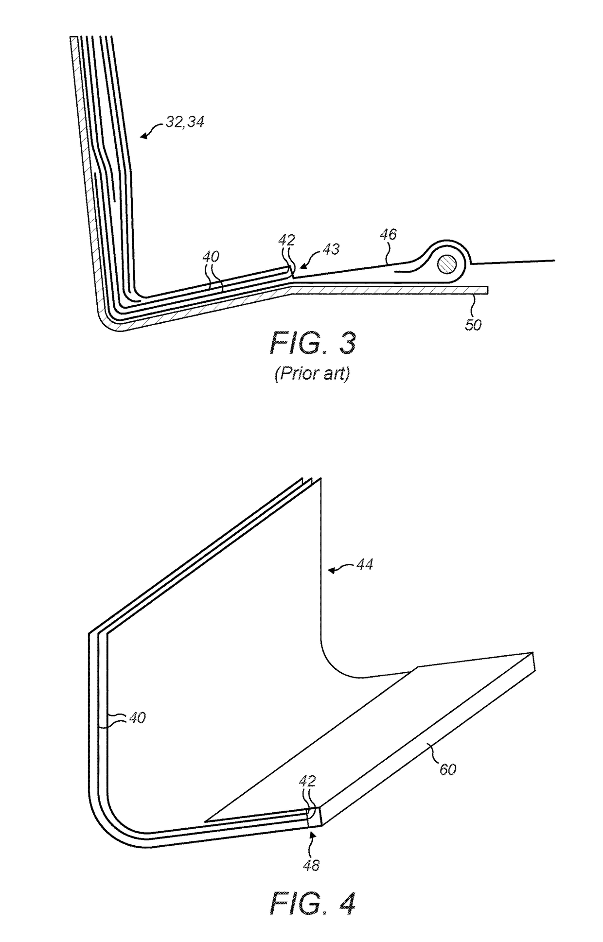
The rough edge 43 may therefore present a safety hazard making the shear web 32, 34 difficult and potentially unsafe to handle.
However, the cured resin is very hard, and a diamond cutting saw is required to cut through the component to trim the edge, making the trimming an expensive and time-consuming process.
However, even in this case the roughness remain to some extent, and the act of de-moulding the component still tends to leave fractured regions of resin that present sharp and hazardous edges.

Method used


Image

  • Composite component having a safety edge
  • Composite component having a safety edge
  • Composite component having a safety edge

Examples


Embodiment Construction

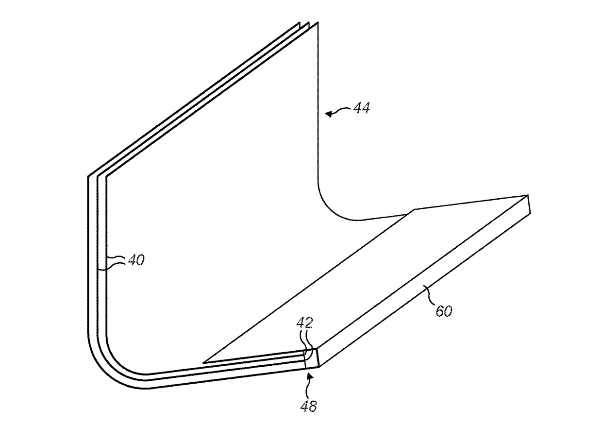
[0040]FIG. 4 illustrates a composite component 130 for a wind turbine blade. In this example, the composite component 130 is a shear web, and FIG. 4 illustrates the bottom part of the shear web only. The shear web 130 comprises a laminate 44 formed by a plurality of laminate layers 40, for example glass-fibre fabric layers, which are integrated together by cured resin. Edges 42 of the laminate layers 40 define a laminate edge 48. A strip of foam 60 extends alongside the laminate edge 48 and is integrated with the laminate 44 by the cured resin. As will be described in further detail later, the strip of foam 60 defines a hand safe edge of the shear web 130, allowing the shear web 130 to be safely handled in use.

[0041]A method of making the shear web 130 will now be described with reference to FIGS. 5A to 5I.

[0042]Referring first to FIG. 5A, to make the shear web 130, a mould tool 50 is provided, which has a mould surface 51 corresponding in shape to the outer contour of the shear web...


PUM

PropertyMeasurementUnit
thicknessaaaaaaaaaa
thicknessaaaaaaaaaa
thicknessaaaaaaaaaa

Abstract

A composite component (130) such as a shear web for a wind turbine blade is described. The component comprises a moulded laminate (44) formed from one or more fibrous layers (40) integrated by resin and defining a laminate edge (48). An edging strip (60) is located adjacent to the laminate edge (48) and is integrated with the laminate. In a particular example, the edging (60) is made from closed-cell foam. Accordingly, resin does not permeate into the bulk of the edging (60) during the moulding process. After the moulding process, a portion (60a) of the edging (60) is removed to reveal an exposed, substantially resin-free surface of the edging which defines a safety edge (64) of the component.

Description

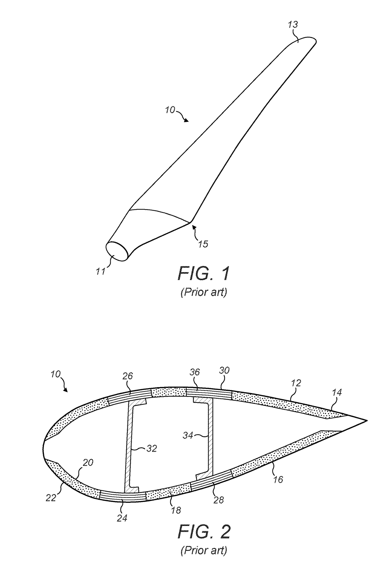
FIELD OF THE INVENTION[0001]The invention relates to composite components having a safety edge to facilitate handling, and to methods of manufacturing such components. The invention has particular application to composite components used in the manufacture of wind turbine blades.BACKGROUND TO THE INVENTION[0002]FIG. 1 illustrates in perspective view a prior art wind turbine blade 10. The wind turbine blade 10 extends longitudinally from a generally cylindrical root 11 to a tip 13. In use, the root end 11 of the blade 10 is attached to a hub of a wind turbine (not shown). In cross-section, the blade 10 transitions from a circular profile at the root 11 to an airfoil profile at the widest part of the blade 10, which is known as the ‘shoulder’15. Between the shoulder 15 and the tip 13, the blade has an airfoil profile that steadily decreases in thickness and chord moving towards the tip 13.[0003]FIG. 2 illustrates the blade 10 in cross-section and reveals that the blade 10 comprises an...

Claims


Application Information

Patent Timeline
Patent Type & Authority Applications(United States)
IPC IPC(8): F03D1/06B29D99/00B29C70/78B32B7/12B32B5/24B32B3/08B32B5/18B29C70/02B32B5/02
CPCF03D1/0683F05B2280/6012B29D99/0025B29C70/78B32B5/02B32B5/245B32B3/08B32B5/18B32B7/12B29L2031/085B32B2266/08B32B2603/00B32B2262/101B29K2309/08B32B2266/0278F05B2240/221F05B2240/301F05B2280/6003F05B2280/6015B29C70/028B29C70/342B29C70/72B29C70/76F03D1/0675Y02E10/74Y02E10/72Y02P70/50B29C70/302F03D80/00F03D1/0633F03D3/062B32B2260/023B32B2260/046
Inventor SANDERCOCK, STEPHENWARDROPPER, STEVE
Owner VESTAS WIND SYST AS
Learn More