Broadband geophone accelerometer

a geophone accelerometer and wideband technology, applied in the field of seismic data acquisition apparatus, can solve the problem of uniform magnitude of the magnetic field between the magnetic block and the inner wall of the geophone sensor housing, and achieve the effect of improving the performance of the geophon

Inactive Publication Date: 2017-07-27
GAO CHUNHUA
View PDF3 Cites 6 Cited by
  • Summary
  • Abstract
  • Description
  • Claims
  • Application Information

AI Technical Summary

Benefits of technology

[0009]Where, the {right arrow over (E)} represents the voltage across the moving coil, {right arrow over (B)} is the magnet field magnitude, {right arrow over (V)} is the velocity of moving coil and the L is the length of the coil wire. Measuring the voltage of the output signal, the mechanical vibration can be calculated by using the equation (1), because both {right arrow over (B)} and L are considering known parameters. Here {right arrow over (B)} is the magnet field magnitude in the space which the moving coil is moving around. However, lots of researchers (for example in U.S. Pat. No. 5,469,408) have already concluded that the magnet field magnitude {right arrow over (B)} of the space between the magnetic block and the inner wall of geophone sensor housing is not uniform. In this magnetic field, the magnet field magnitudes {right arrow over (B)} in some area are not equal to each other, because they might have different values or different direction. Only the magnet field magnitude of the area, where it is close to the shoulder face of the bobbin, could be considered as uniform. Therefore, in the coil's moving area, it is not accurate to put the magnet field magnitude {right arrow over (B)} as a constant by using equation (1). This could be the reason that the current moving coil geophone has higher THD. In the disclosure, coils are assembled separated in different recesses of the bobbin and the measuring coils are located in the most well distributed magnet field (or uniformed field). For example, the sensing coil is strictly assembled in the space of which they have the well distributed magnet field magnitude {right arrow over (B)}. The moving coil's height along the geophone housing's cylindrical axis is designed to match the height of magnetic boot shoulder face. And the sensing coil's moving path is controlled by driving coil (described below) and less than + / −0.0002 mm (the current most moving coil geophones have + / −2 mm). These will highly improve the performances of geophones.
[0011]By injecting a current {right arrow over (I)} to a coil, a force is generated using equation (2). The direction of the force is determined by the direction of the current. Therefore, a close loop system can be set up by putting one coil as measuring component and the other coil as the controller. For the purpose of minimizing the geophone dimensions and putting the measuring coil in the uniformed magnet field, both of the first coil set and the second coil set are wound to the bobbin separately. The first coil set (or the sensing coil) is wound to recesses which will have the most well distributed magnet field magnitude; the second coil set (or driving coil) is wound to recesses which will have the less well distributed magnet field magnitude. Therefore, the bobbin is designed to have four (4) recesses. The top recess and the bottom recess will be wound for sensing coil set and are assembled in the area of well-distributed magnet field magnitude. The middle two recesses are wound by two coils of the driving coil set. Located in separated recesses of the bobbin, each coil portion of these coil sets has an individual magnet field magnitude by using faraday's law (or equation (1)) and Lorentz's law (or equation (2)). By this mathematic method, the performances of the sensor are highly improved. Both the two coil sets are connected to an electronic device which processes the measuring signal and feedbacks the signal as a precision digital forcing signal to sensing coil as a reference position. The same methods also apply to magnetic block moving sensors which their coils and bobbin is stably assembled with housing.

Problems solved by technology

However, lots of researchers (for example in U.S. Pat. No. 5,469,408) have already concluded that the magnet field magnitude {right arrow over (B)} of the space between the magnetic block and the inner wall of geophone sensor housing is not uniform.

Method used


Image

  • Broadband geophone accelerometer
  • Broadband geophone accelerometer
  • Broadband geophone accelerometer

Examples


Embodiment Construction

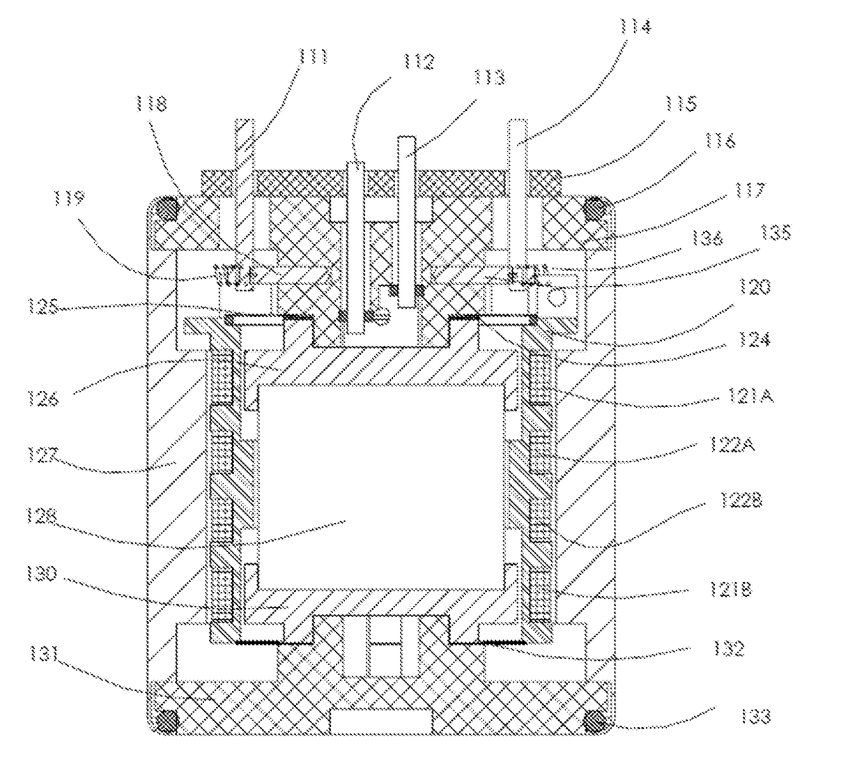
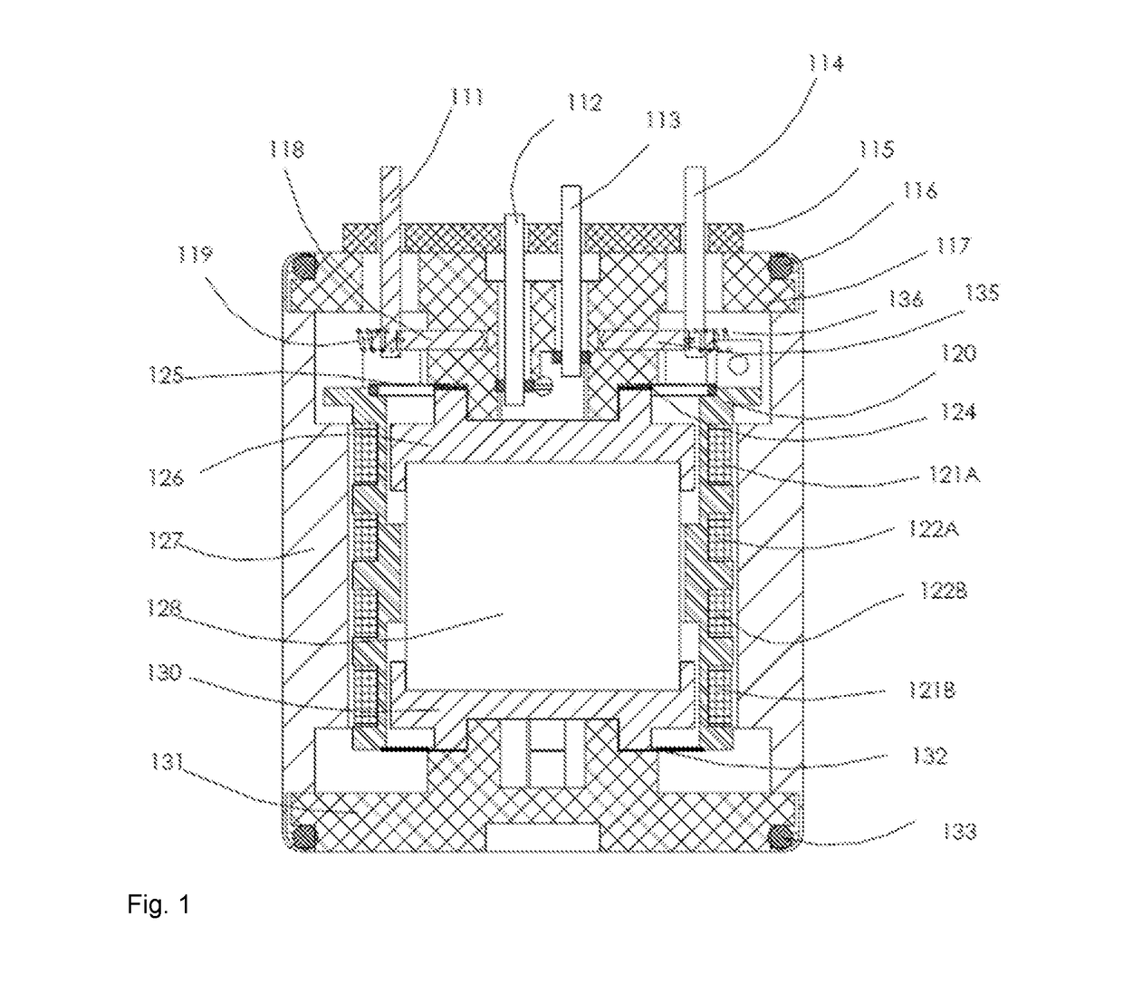
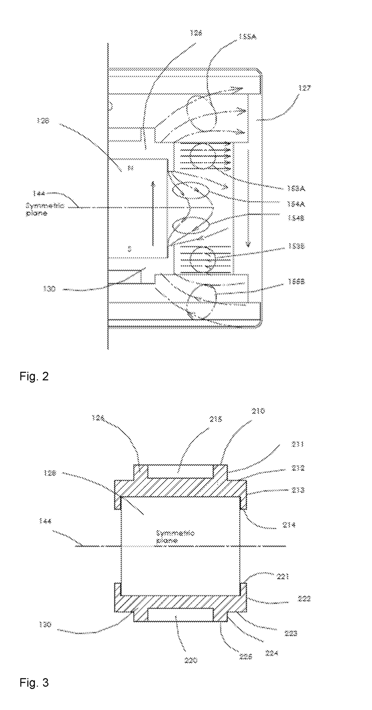
[0022]FIG. 1 shows the structure of the new geophone invention. Top convert board 115 is used for connection between inner coil sets and electronic processing device. While mounting to the top convert board 115, the 4 terminal pins (111,112,113,114) are connected to inner sensing coil 121 and driving coil 122. For protecting the pins, the electronic processing device is connected to the pins through the PCB convert board 115. Cap 117 is mounted to housing 127 with a top o-ring 116 for sealing. Pin 112 is connected to one end of sensing coil set by electric connection among top magnetic boot 126, magnetic block 128, bottom magnetic boot 130, and bottom spring 132 using the well-known technologies in this industry. Similarly, pin 113 is connected to another end of sensing coil set 121 by top spring 125. The top end of sensing coil set is soldered to top spring 125 which is isolated with top magnetic boot 126 using an insulation disc 124. The terminal 111 is connected to one end of dri...


PUM


Abstract

A closed loop broadband geophone which is made by using a high performance method to measure a mechanical vibration is disclosed. All coil portions of the two or more coil sets are located in at least 4 separate recesses of the bobbin. Each coil portion of these coil sets has an individual magnetic field magnitude using Faraday's Law and Lorentz's Law. This mathematic method, significantly improves the accuracy of both measuring the mechanical vibration and providing feedback control to the sensor coils. These coil sets are connected to an electronic device which processes the measuring signal and a feedback signal to the sensing coil as a precision digital forcing signal for a reference position.

Description

[0001]This application claims the benefit of U.S. Provisional Application Ser. No. 62 / 110,542, filed on Feb. 1, 2015.FIELD OF THE DISCLOSURE[0002]The present disclosure generally relates to a seismic data acquisition apparatus, and in particular, a multiple-coil, multiple-terminal geophone accelerometer.BACKGROUND[0003]1. Field of the Invention[0004]This invention relates generally to the field accelerometers, and in particular to methods and closed loop accelerometers, and more specifically to an accelerometer used in a seismic data acquisition system, micro seismic monitoring / acquisition system.[0005]2. Description of the Prior Art[0006]It is well known that the current conventional geophones are still widely used in seismic exploration to acquire / measure the vibration signal from the ground, primarily due to low cost, lack of reliance on power and high reliability. However, current conventional geophones are still unsatisfactory due to their narrow frequency bandwidth, and high t...

Claims


Application Information

Patent Timeline
Patent Type & Authority Applications(United States)
IPC IPC(8): G01V1/18
CPCG01V1/182
Inventor GAO, CHUNHUA
Owner GAO CHUNHUA
Why Eureka
Try Eureka