Loading station for transferring frozen samples at low temperatures

a technology for loading stations and frozen samples, applied in the direction of microscopes, instruments, electric discharge tubes, etc., can solve the problems of not only requiring a considerable amount of time, but also unable to transfer samples from one sample holder into a different configuration sample holder for a different application

Active Publication Date: 2017-07-27
LEICA MICROSYSTEMS GMBH
View PDF3 Cites 10 Cited by
  • Summary
  • Abstract
  • Description
  • Claims
  • Application Information

AI Technical Summary

Benefits of technology

[0007]An object of the invention is therefore to make possible maximally contamination-free translocation of a frozen sample from one sample holder into a differently configured sample holder, or into a differently configured sample transfer device, which is provided for a different application.
[0012]The frozen samples are very small electron microscopy samples that can be translocated by means of the loading station according to the present invention into the different sample holders of the various processing devices or analytical devices. In the context of the correlative methods between a light microscope and electron microscope already mentioned above (CLEM, correlative light-electron microscopy), the frozen electron microscopy samples are investigated using both a light microscope and an electron microscope. The loading station according to the present invention also enables simple translocation of a frozen electron microscopy sample into sample holders that are embodied for light and electron microscopy.
[0016]In an advantageous refinement, the loading station is characterized by a reservoir container for the coolant, which is connected to the chamber via a controllable inlet valve for the coolant. The controllable inlet valve is controlled, for example, via a stepping motor. Advantageously, a fill level sensor, with which coolant delivery from the reservoir container into the chamber is regulatable via the controllable inlet valve, is arranged in the chamber. Regulation of the coolant delivery into the chamber guarantees automatic replenishment of the coolant into the chamber, and thus continuous cooling of the samples.
[0022]The chamber of the loading station is configured to be open toward the top. Continuous evaporation of the coolant results in formation of a flow of cold gas that emerges from the chamber and thus prevents air from entering. In the context of a particularly advantageous variant, the loading station comprises a breath shield that is positioned above the chamber that is open toward the top. The breath shield prevents water vapor from freezing in or on the chamber. The emerging flow of cold gas and the breath shield prevent contamination of the samples.
[0023]In an advantageous variant, an air lock, which by means of a vacuum pump respectively permits evacuation of a sample transfer device as well as transfer of the frozen sample into an evacuatable sample transfer device and transfer of the frozen sample out of an evacuatable sample transfer device, is attachable to the chamber. Transfer under vacuum prevents contamination, and ensures better cooling of the sample (heat transfer only by radiation; almost no gas convection). One sample transfer device that is provided for cryo-transfer of frozen samples under vacuum or in an inert gas atmosphere is the aforementioned Leica EM VCT100 Shuttle (manufacturer: Leica Microsystems). Sample transfer devices for cryo-transfer under vacuum or in inert gas possess a container that, for transfer, is evacuated or can be filled with inert gas. The frozen samples are transferred into and out of the container via an air lock. Air locks of this kind are known per se and, for example, are constructed so that they are delimited by two slide valves, a vacuum being producible in the cavity between the slide valves by corresponding positioning of the slide valves. One slide valve can be fastened on the sample transfer device; the other slide valve is fastened on the loading station port. The air lock is formed by docking the sample transfer device onto the loading station port, for example via a hooking apparatus, and is sealed off from the outside, for example, by means of O-rings. The sample transfer device advantageously possesses a slide rod on which the sample holder having a sample is secured. The sample holder can then be transferred by means of the slide rod through the air lock from the loading station into the sample transfer device, and vice versa.

Problems solved by technology

With the known loading station described above, translocation of a sample from one sample holder into a differently configured sample holder for a different application is not possible.
This not only involves a considerable expenditure of time, but encompasses critical working steps in which the samples can become damaged or contaminated.

Method used


Image

  • Loading station for transferring frozen samples at low temperatures
  • Loading station for transferring frozen samples at low temperatures
  • Loading station for transferring frozen samples at low temperatures

Examples


Embodiment Construction

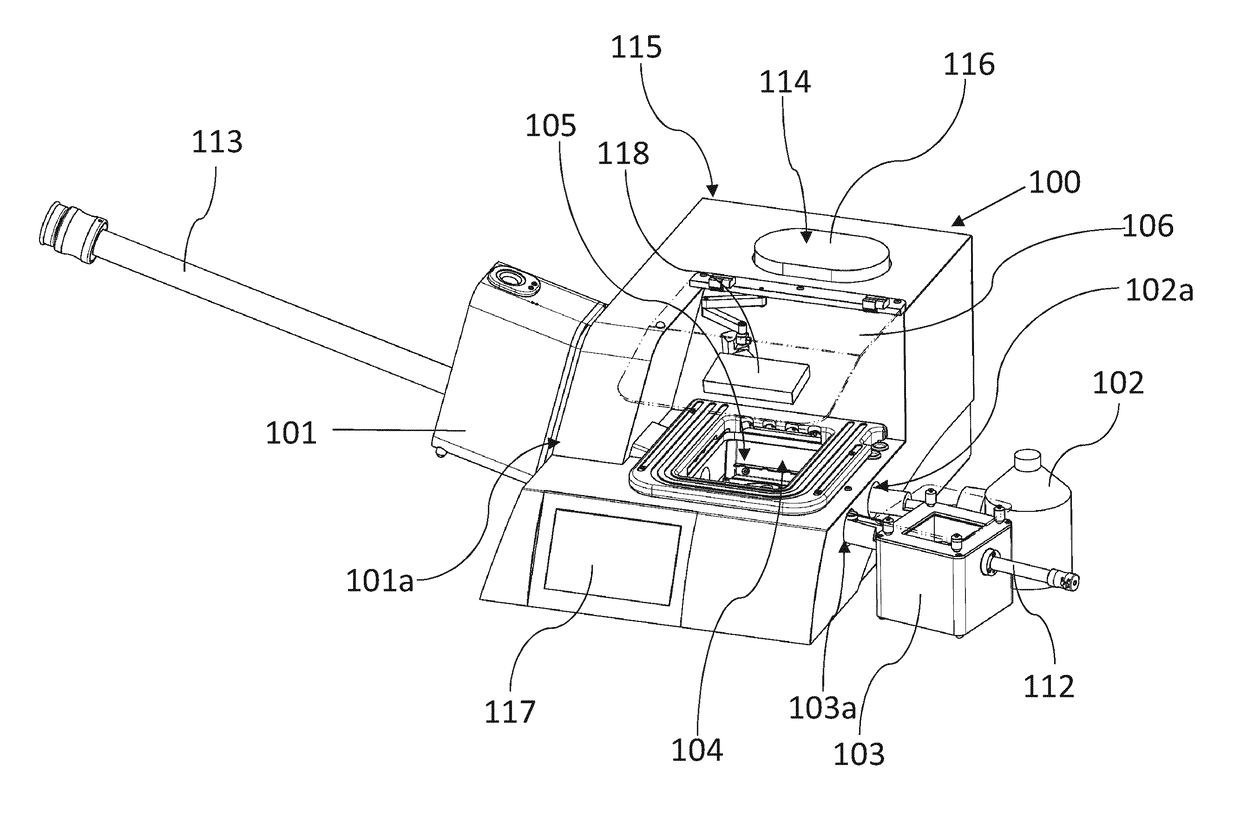
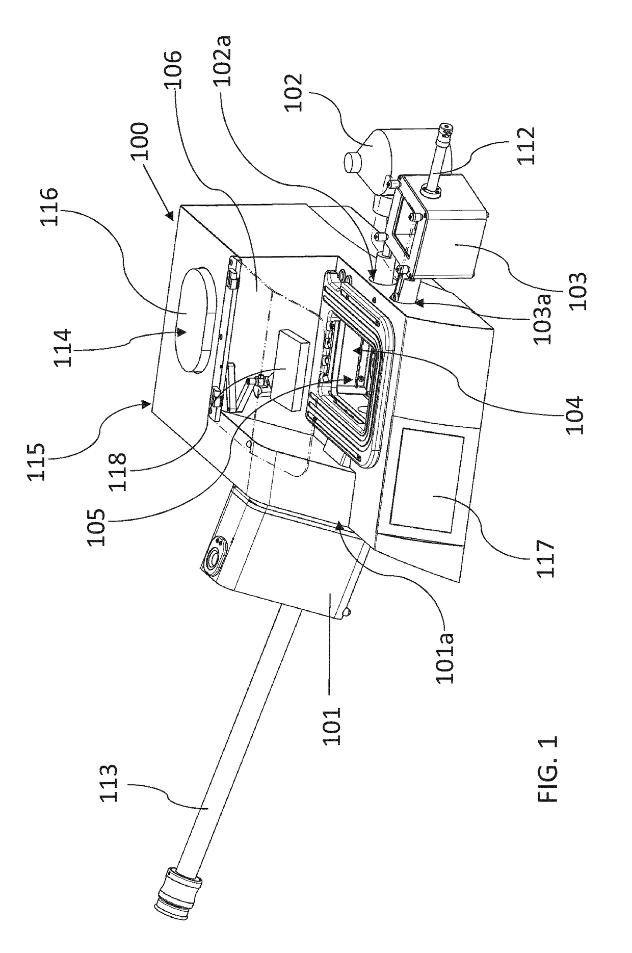
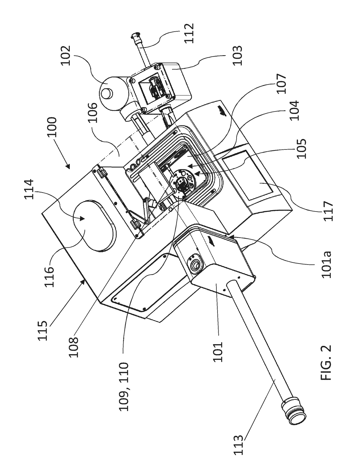
[0034]FIG. 1 and FIG. 2 are perspective views of a loading station 100 in accordance with the invention. Loading station 100 encompasses a chamber 104, cooled with coolant (in the example, liquid nitrogen (LN2)), which is open toward the top. In the example shown, chamber 104 is embedded into a housing 115. Chamber 104 is filled at least partly with LN2. Continuous evaporation of the coolant results in formation of a flow of cold gas that emerges from chamber 104 and thereby prevents the entry of air. A breath shield 106 is positioned above open region 105 of chamber 104. The breath shield prevents water vapor from freezing in or on the chamber. The emerging flow of cold gas, and the breath shield, thus prevent contamination of the samples. The loading station furthermore possesses a magnifying lens (loupe) 118 that is positioned above chamber 104 and below breath shield 106.

[0035]The samples are very small frozen samples for electron microscopy, which are transferred into and out o...


PUM

PropertyMeasurementUnit
temperatureaaaaaaaaaa
temperaturesaaaaaaaaaa
electron microscopyaaaaaaaaaa

Abstract

A loading station (100, 200) for translocating a frozen sample for electron microscopy, encompassing a chamber (104, 204), open toward the top, that is fillable at least partly with a coolant, the chamber (104, 204) comprising in its side wall at least two ports (101a, 102a, 103a) each for different sample transfer devices (101, 102, 103), the ports (101a, 102a, 103a) permitting introduction of a frozen sample into the chamber (104, 204) via a selected sample transfer device and withdrawal of a frozen sample from the chamber via a respective different sample transfer device; and wherein a receptacle (108, 208) for at least two differently configured sample holders (109, 110) is arranged in the chamber (104, 204), the at least two sample holders (109, 110) being detachably fastenable to at least one of the sample transfer devices (101) for introduction of the frozen sample into the chamber (104, 204) and for withdrawal of the frozen sample from the chamber (104, 204).

Description

CROSS-REFERENCE TO RELATED APPLICATIONS[0001]The present application is the U.S. national phase of International Application No. PCT / EP2015 / 066106 filed Jul. 15, 2015, which claims priority of German Application No. 10 2014 110 722.5 filed Jul. 29, 2014, the entirety of which is incorporated herein by reference.FIELD OF THE INVENTION[0002]The invention relates to a loading station for translocating a frozen sample for electron microscopy, encompassing a chamber, open toward the top, that is fillable at least partly with a coolant.BACKGROUND OF THE INVENTION[0003]Cryofixation is a sample preparation method often used in electron microscopy. In this, a water-containing sample is frozen very rapidly to a temperature below −150° C. (cryofixed), i.e. it is cooled very quickly while avoiding the formation of ice crystals. Cryofixation has proven to be particularly suitable for investigations of structural biology. The specimens to be investigated, for example cells, enzymes, viruses, or l...

Claims


Application Information

Patent Timeline
Patent Type & Authority Applications(United States)
IPC IPC(8): H01J37/20G02B21/00G01N1/42H01J37/26H01J37/18
CPCH01J37/20H01J37/26H01J37/18H01J2237/262G02B21/00H01J2237/16H01J2237/20221G01N1/42G01Q30/20G01N1/06G01N1/32
Inventor LIHL, REINHARDGAECHTER, LEANDER
Owner LEICA MICROSYSTEMS GMBH
Why Eureka
Try Eureka