Method to protect a power converter arrangement and power converter arrangement with a protective device

a technology of protection device and power converter, which is applied in the direction of power conversion system, ac-dc conversion, electrical apparatus, etc., can solve the problems of inability to turn off, the thyristor turn-off time cannot be precisely controlled or guaranteed, and the freewheeling diodes of the power converter and the brake choppers must be greatly over-rated to cope with the transient rotor surge current. , to achieve the effect of reducing the stress on their components

Active Publication Date: 2017-07-27
GE ENERGY POWER CONVERSION TECH
View PDF17 Cites 14 Cited by
  • Summary
  • Abstract
  • Description
  • Claims
  • Application Information

AI Technical Summary

Benefits of technology

[0012]In accordance with a first aspect of the invention, a method is provided to protect a power converter arrangement. The power converter arrangement has a power converter device that has a direct current DC side connected with a DC intermediate circuit, an alternating current (AC) side, and controllable switching elements that can be controllably switched at a relatively high frequency to convert the DC voltage of the DC intermediate circuit into a multi-phase AC voltage to feed the AC side. The method provides a protective device, that can be activated and deactivated, to protect the power converter device from overload by connecting a rectifier circuit having rectifier elements, at least one of which is formed by thyristors, to the AC side of the power converter device, and connecting a bypass branch to a DC side of the rectifier circuit, the bypass branch having a brake resistor that serves, when necessary, to transform energy dissipated from the AC side of the power converter device into thermal energy. The method also provides that in case a predetermined error situation is detected, the thyristors of the rectifier circuit are triggered to turn them on, to activate the protective device, to rectify, by means of the rectifier circuit, AC voltage energy from the AC side of the power converter device and feed it to the bypass branch including the brake resistor. The method also provides that if disappearance of the pred

Problems solved by technology

The major disadvantage of this solution is that the freewheeling diodes of the power converter and the brake choppers must be greatly over-rated to cope with the transient rotor surge currents.
Unfortunately, once the thyristors are activated they cannot be turned off until the rotor currents naturally or forcedly fall to zero.
Since the rotor transient current can contain both DC and low-frequency components, the rotor currents might not have any zero crossing for a prolonged period of time,

Method used


Image

  • Method to protect a power converter arrangement and power converter arrangement with a protective device
  • Method to protect a power converter arrangement and power converter arrangement with a protective device
  • Method to protect a power converter arrangement and power converter arrangement with a protective device

Examples


Embodiment Construction

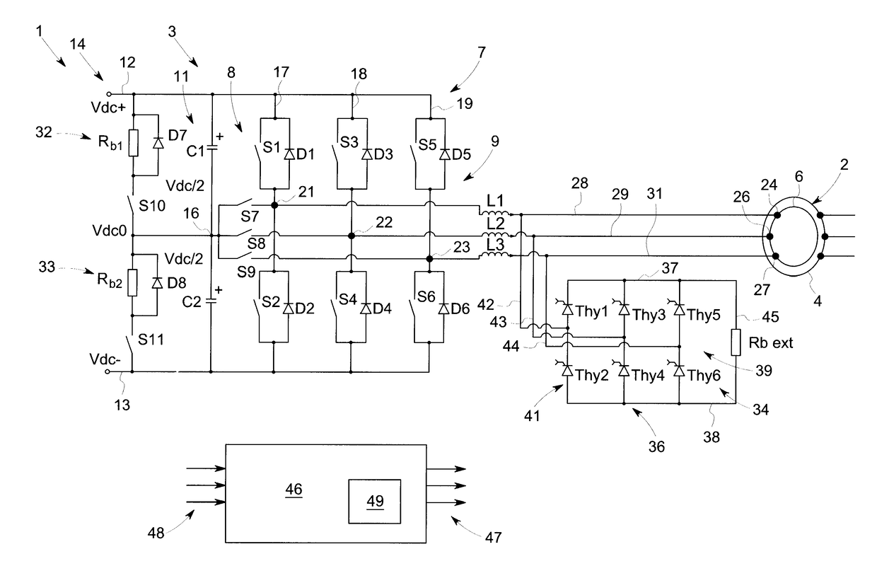
[0043]FIG. 1 shows a simplified block diagram of an exemplary drive system 1 in which an embodiment of the invention can be implemented. The illustrated system 1 is a so-called DFIM system with a doubly fed induction machine (doubly fed induction machine or generator, DFIG) 2, whose rotor current can be controlled through a power converter arrangement 3. Even though embodiments of the invention are described below in connection with a DFIM system, is the embodiments are equally applicable to other systems in which a power converter arrangement is used to produce, from its direct voltage (DC) input, an alternating voltage or alternating current (AC) output at its output, with which a connected load can be fed, if the load can, in case of malfunction, produce surge currents or other current or voltage transients that could damage the power converter arrangement. In this respect, the area of application of embodiments of the invention is not limited to use in connection with doubly fed...


PUM


Abstract

A method is disclosed to protect a power converter arrangement with a power converter that has a DC side that is connected to a DC intermediate circuit, an AC side, and controllable switches that can be controllably switched at a high frequency to invert the DC voltage of the DC intermediate circuit into an AC voltage. A protective device that can be activated and deactivated is provided to protect the power converter from overload by connecting an external thyristor rectifier bridge with a brake resistor (Rb ext) to the AC side of the power converter. If a predetermined error situation is detected, the external thyristors are triggered to turn on, to activate the protective device. If it is detected that the predetermined error situation has disappeared, the external thyristors are turned off. A power converter arrangement with a device to protect against overload is also disclosed.

Description

TECHNICAL FIELD[0001]Embodiments of the present invention relate to a method to protect a power converter arrangement and a power converter arrangement with a protective device, in particular a method and a device to deactivate a thyristor-based protective device for a power converter arrangement.BACKGROUND[0002]Power converter arrangements are used in many applications, among other things for generator and motor drives. A power converter arrangement usually comprises a power converter whose direct current (DC) side is connected to a DC intermediate circuit whose alternating current (AC) side is connected with an AC voltage grid and / or an electrical load, such as, for example, a rotating electrical machine or a transformer, and that has controllable switching elements that can be controllably switched at a high-frequency to convert the DC voltage of the DC intermediate circuit into a multiphase AC voltage to feed the AC side. A controller controls the operation of the power converte...

Claims


Application Information

Patent Timeline
IPC IPC(8): H02M7/48H02M1/084H02M1/32
CPCH02M7/48H02M2001/0009H02M1/0845H02M1/32H02H7/122H02H7/1227H02M7/5387H02M1/0009
Inventor BASIC, DUROROTHENHAGEN, KAI ALEXANDER
Owner GE ENERGY POWER CONVERSION TECH
Why Eureka
Try Eureka