Gearbox Planet Squeeze Film Damper

a technology of squeeze film and planet gearbox, which is applied in the direction of elastic bearings, machines/engines, etc., can solve the problem that variable dynamic issues invariably arise, and achieve the effect of maximizing the bearing's dynamic tolerance capability, reliability and useful life, and improving the engine's time in active servi

Active Publication Date: 2017-08-03
GENERAL ELECTRIC CO
View PDF1 Cites 21 Cited by
  • Summary
  • Abstract
  • Description
  • Claims
  • Application Information

AI Technical Summary

Benefits of technology

[0011]Each of the above exemplary embodiments of the present disclosure adds damping to the system in a very compact and efficient manner by incorporating the squeeze film damper directly into the planet bearing itself. Each of these embodiments maximizes the b...

Problems solved by technology

Because each planet gearbox that houses each planet gear is disposed within the flow path of the gas turbine engine, the challenge is to design on the one hand a reliable and robust planet gearbox that meets all flight conditions of the engine while on the other hand designing a planet gearbox th...

Method used


Image

  • Gearbox Planet Squeeze Film Damper
  • Gearbox Planet Squeeze Film Damper
  • Gearbox Planet Squeeze Film Damper

Examples


Embodiment Construction

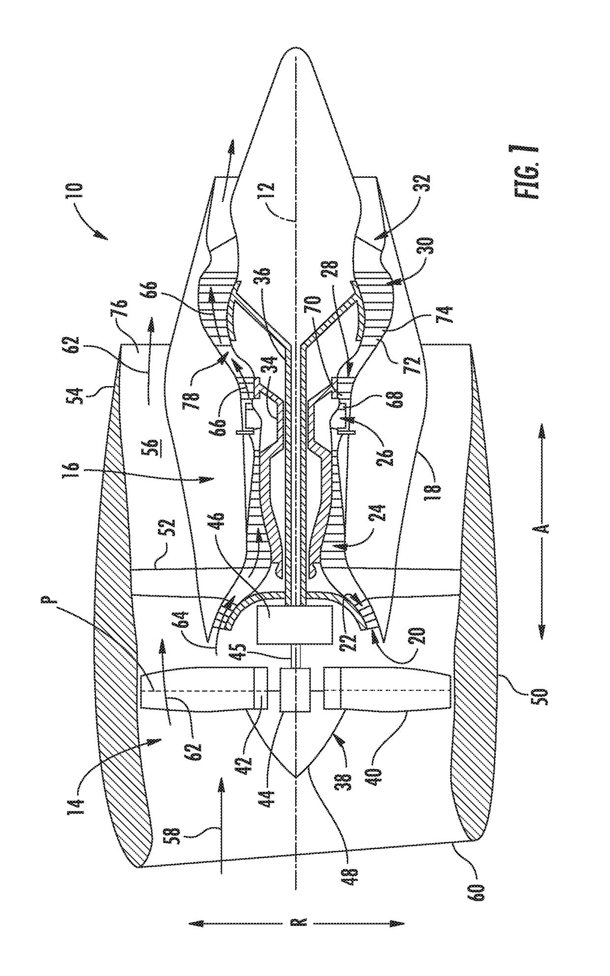
[0020]Reference will now be made in detail to present embodiments of the invention, one or more examples of which are illustrated in the accompanying drawings. The detailed description uses numerical and letter designations to refer to features in the drawings. Like or similar designations in the drawings and description have been used to refer to like or similar parts of the invention. As used herein, the terms “first”, “second”, and “third” may be used interchangeably to distinguish one component from another and are not intended to signify location or relative importance of the individual components. The terms “upstream” and “downstream” refer to the relative direction with respect to fluid flow in a fluid pathway. For example, “upstream” refers to the direction from which the fluid flows, and “downstream” refers to the direction to which the fluid flows. As used herein, the fluid can be a gas such as air or a liquid such as a lubricant.

[0021]Referring now to the drawings, wherei...


PUM


Abstract

An epicyclic gearing arrangement includes a planet gear rotatable on a planet bearing that is mounted via a support pin to a carrier of the epicyclic gearing arrangement. A spring film damper is disposed between the outer surface of the bearing's outer ring and the opposing inner surface of the planet gear and includes an annular gap. The support pin and/or outer ring include oil feed holes that open into the respective annular gap(s).

Description

FIELD OF THE INVENTION[0001]The present subject matter relates generally to a cylindrical roller bearing, or more particularly to a cylindrical roller bearing for the planet gear in an epicyclic gearbox in a gas turbine engine.BACKGROUND OF THE INVENTION[0002]A gas turbine engine generally includes a fan and a core arranged in flow communication with one another with the core disposed downstream of the fan in the direction of the flow through the gas turbine. The core of the gas turbine engine generally includes, in serial flow order, a compressor section, a combustion section, a turbine section, and an exhaust section. With multi-shaft gas turbine engines, the compressor section can include a high pressure compressor (HP compressor) disposed downstream of a low pressure compressor (LP compressor), and the turbine section can similarly include a low pressure turbine (LP turbine) disposed downstream of a high pressure turbine (HP turbine). With such a configuration, the HP compressor...

Claims


Application Information

Patent Timeline
IPC IPC(8): F16H57/00F16H57/08F02C7/36F16H1/28
CPCF16H57/0006F16H1/28F16H57/082F05D2260/96F16H2057/0012F05D2260/40311F02C7/36F16H57/0469F16H57/08F16H2057/085F16H57/0471F16C19/28F16C2361/61F16C27/045F16C2360/23
Inventor NIERGARTH, DANIEL ALANMILLER, BRANDON WAYNEERTAS, BUGRA HANBRADLEY, DONALD ALBERTDICKMAN, JOSEPH ROBERT
Owner GENERAL ELECTRIC CO
Why Eureka
Try Eureka