Rotary union with integral sensor array

a sensor array and rotary technology, applied in the direction of hose connection, fluid tightness measurement, instruments, etc., can solve the problems of high media pressure, high flow rate, high cost and/or difficult repair or replacement of precision components, and components that are often subject to corrosive environments or damag

Active Publication Date: 2017-08-03
DEUBLIN
View PDF2 Cites 17 Cited by
  • Summary
  • Abstract
  • Description
  • Claims
  • Application Information

AI Technical Summary

Benefits of technology

[0009]The disclosure describes, in one aspect, a rotary union configured for transferring a fluid. The rotary union includes a housing having a media channel therein, the housing further having a pocket, the pocket being fluidly isolated from the media channel; a rotating machine component rotatably supported in the housing; a rotating seal member associated with the rotating machine component; a non-rotating seal member slidably and sealably disposed within the housing adjacent the rotating seal member; and a sensor array disposed in the pocket, the sensor array including a plurality of sensing elements that are integrated with a control device and a communication device. The sensor array is fluidly isolated from the media channel when the non-rotating seal member is in contact with the rotating seal member to form a mechanical face seal.
[0010]In another aspect, the disclosure describes a rotary device. The rotary device includes a housing made from a non-metallic material, a rotating machine component rotatably supported in the housing, a rotating member associated with the rotating machine component, a non-rotating member disposed within the housing adjacent the rotating member, and a sensor array disposed in the housing. The sensor array includes a plurality of sensing elements that are integrated with a control device and a wireless communication device. The wireless communication device is configured to communicate with a central control that is remotely located relative to the housing using electromagnetic waves. The wireless communication device is arranged to remain in communication with the central control for any mounting orientation of the housing relative to the sensor array and the central control.

Problems solved by technology

Often these applications require relatively high media pressures, flow rates, or high machine tool rotational speeds.
Machines using rotary unions typically include precision components, such as hearings, gears, electrical components, and others, that are expensive and / or difficult to repair or replace during service.
These components are often subject to corrosive environments or to damage if exposed to fluid leaking or venting from the rotary union during operation.
Fluid leaking from a union is also typically undesirable.
When a rotary union is used with non-lubricating media (such as dry air) or without any media, the engaged seal surfaces experience a “dry running” condition, which causes rapid seal wear due to lack of adequate lubrication.
Extended periods of dry running can cause severe damage to the seal members, thereby requiring expensive and time-consuming replacement of one or both seal members.
For example, rotary unions having seal surfaces that disengage when opposing fluid pressures are present, such as the arrangement disclosed in U.S. Pat. No. 5,538,292, can be complex and expensive to manufacture.
Rotary unions having seal surfaces that disengage automatically in the absence of media, such as the arrangement disclosed in U.S. Pat. No. 4,976,282, are less complex to manufacture and incorporate in a machine, but are prone to engagement of the seal surfaces when non-lubricating media is used.
Seal surfaces with special geometries for non-contacting operation with gases, such as those disclosed in U.S. Pat. Nos. 6,325,380 and 6,726,913, do not provide effective sealing with liquid media.
Rotary unions that engage the seal surfaces at all times, even with a reduced bias, such as the unions disclosed in U.S. Pat. No. 6,929,099, are prone to damage from dry running at high rotating speeds.
However, even with use of improved sealing and mechanisms to avoid dry running of unions, any union will eventually require repair or replacement.
Such and other measures typically have costly consequences.
Periodic inspections of unions are also time consuming and costly as unions are typically found within a machine and require effort by a technician to access them and assess their condition.

Method used


Image

  • Rotary union with integral sensor array
  • Rotary union with integral sensor array
  • Rotary union with integral sensor array

Examples


Embodiment Construction

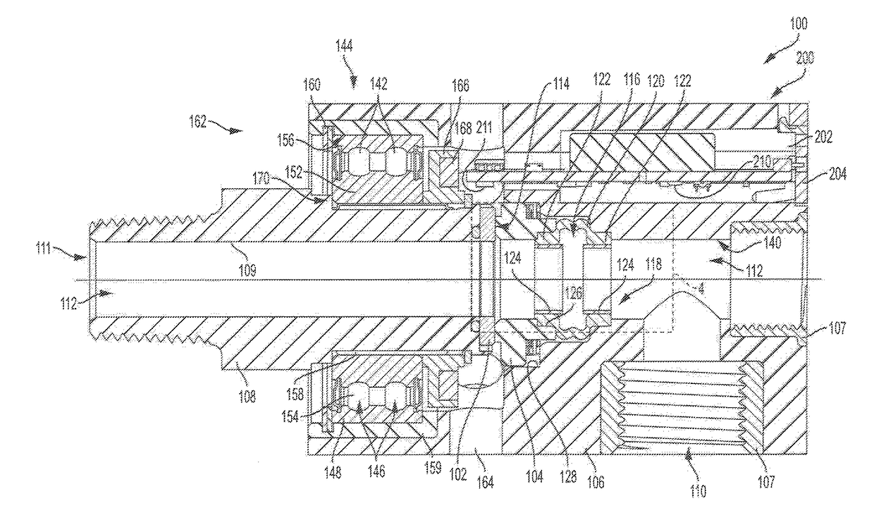
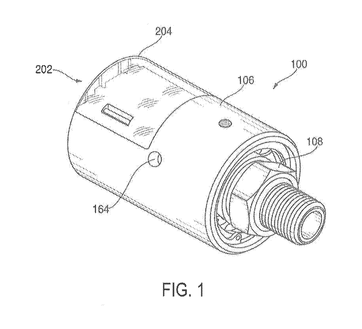
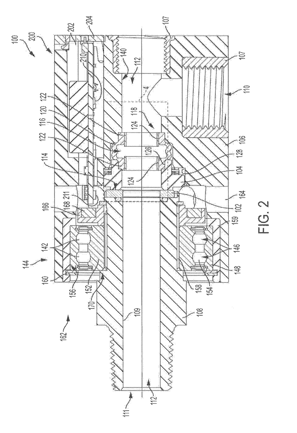
[0019]In the drawings, which form a part of this specification, FIG. 1 shows a perspective view of a rotary union 100, and FIG. 2 shows a section view through the rotary union 100 to illustrate various internal components. It should be appreciated that in the exemplary embodiments shown herein, a rotary union is illustrated but the systems and methods described in the present disclosure are equally applicable to any rotary device that includes stationary and fully or partially rotatable components in sliding contact with one another. Examples of rotary devices, therefore, can include rotary unions or swivel joints, which are used to convey fluids through fully or partially rotatable joints or components, and can also include devices for connecting electrical leads across fully or partially rotatable interfaces such as slip rings. In reference to the exemplary rotary union illustrated herein, the rotary union 100 includes a rotating seal member 102 and a non-rotating seal member 104 ...


PUM

PropertyMeasurementUnit
axial lengthaaaaaaaaaa
pressureaaaaaaaaaa
moldingaaaaaaaaaa

Abstract

The disclosure describes a rotary device that includes a housing, a rotating machine component, a rotating member associated with the rotating machine component, a non-rotating member disposed within the housing adjacent the rotating member, and a sensor array disposed in the housing. The sensor array includes a plurality of sensing elements that are integrated with a control device and a wireless communication device. The wireless communication device is configured to communicate with a central control that is remotely located relative to the housing using electromagnetic waves.

Description

CROSS-REFERENCE TO RELATED APPLICATIONS[0001]The present application claims the benefit of U.S. Provisional Patent Application Ser. No. 62 / 289,659, filed on Feb. 1, 2016, which is incorporated herein in its entirety by this reference.TECHNICAL FIELD OF THE DISCLOSURE[0002]The present invention relates to rotary devices such as rotary unions, swivel unions, slip rings and the like.BACKGROUND OF THE DISCLOSURE[0003]Fluid coupling devices such as rotary unions are used in industrial applications, for example, machining of metals or plastics, work holding, printing, plastic film manufacture, papermaking, and other industrial processes that require a fluid medium to be transferred from a stationary source such as a pump or reservoir into a rotating element such as a machine tool spindle, work-piece clamping system, or rotating drums or cylinder. Often these applications require relatively high media pressures, flow rates, or high machine tool rotational speeds.[0004]Rotary unions used in...

Claims


Application Information

Patent Timeline
Patent Type & Authority Applications(United States)
IPC IPC(8): F16L55/00F16L27/087
CPCF16L27/087F16L55/00B23Q17/007F16L27/0828Y10T29/49826B23Q1/70B23Q11/103G01M3/183F16L27/082F16L27/0804
Inventor PETROU, ANTON A.BUDZUS, CHRISTOPHGULIANA, SARGON
Owner DEUBLIN
Why Eureka
Try Eureka