Magnetic flux coupling structures with controlled flux cancellation

a technology of magnetic flux and coupling structure, which is applied in the direction of electric vehicle charging technology, charging station, transportation and packaging, etc., can solve the problems of brittleness and expensive, easy damage of ferrite,

Active Publication Date: 2017-08-03
AUCKLAND UNISERVICES LTD
View PDF4 Cites 16 Cited by
  • Summary
  • Abstract
  • Description
  • Claims
  • Application Information

AI Technical Summary

Benefits of technology

[0006]It is an object of the present invention to provide an inductive power transfer flux coupling apparatus or module, or method of wireless or inductive power transfer which

Problems solved by technology

Ferrite has disadvantages which include being brittle and expensive.
In particular, in a vehicle and roadway environment, ferrite is easily damaged.
The disadvantages of ferrite also extend to other applications such as charging other apparatus such as mobile telephones.
Efficient maximisation

Method used


Image

  • Magnetic flux coupling structures with controlled flux cancellation
  • Magnetic flux coupling structures with controlled flux cancellation
  • Magnetic flux coupling structures with controlled flux cancellation

Examples


Embodiment Construction

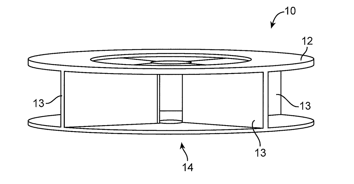
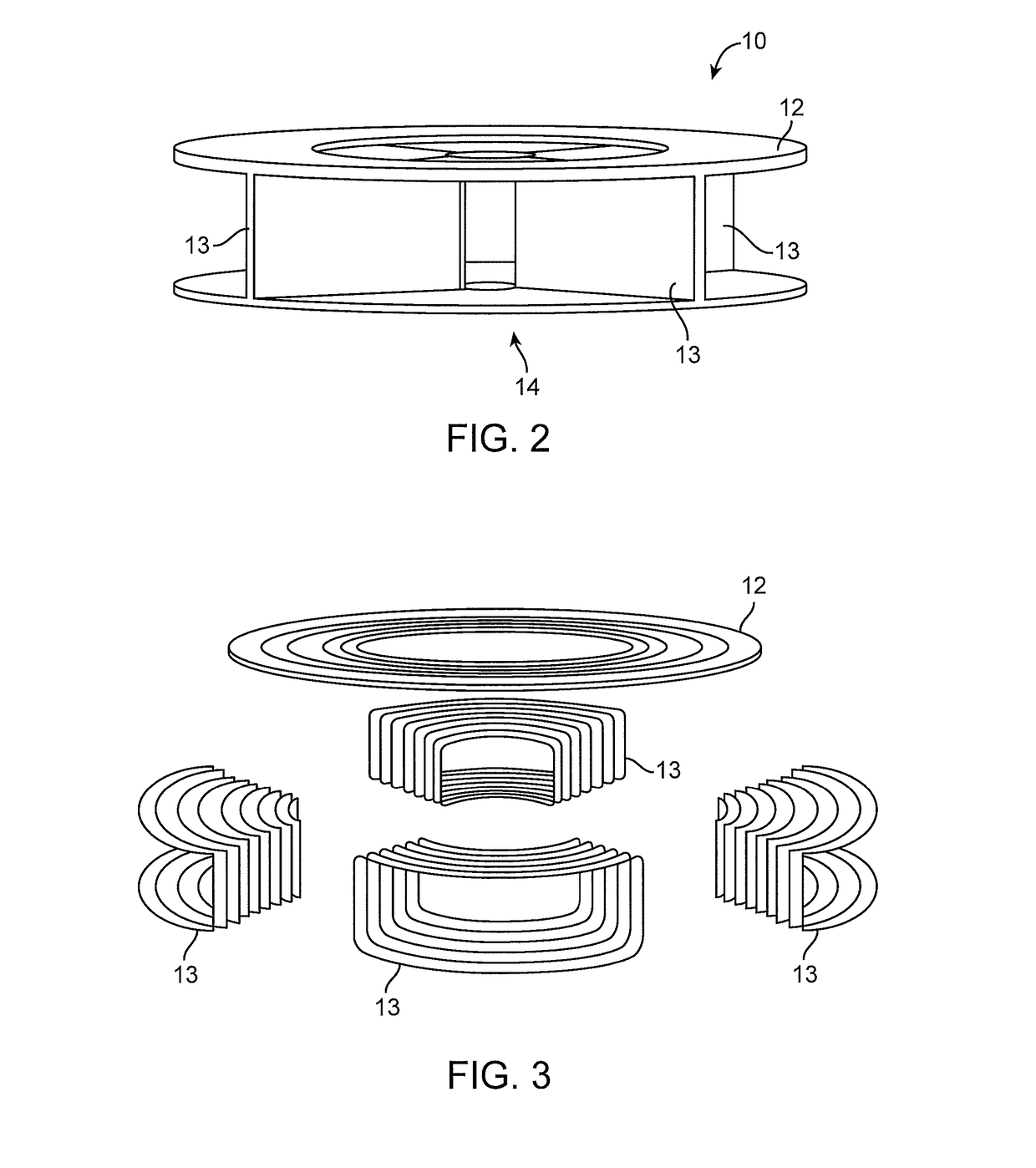
[0163]The inductive power transfer apparatus described below may be provided in the form of a pad, and for purposes of convenience is referred to in this document as a pad or power transfer module despite being capable of being provided in other forms. These new pads may have no ferrite in them, and in at least one embodiment there is no ferrite at all. In consequence, the construction of a pad can be very different from those presently known. The new pads can be made simply using concrete, or another suitably robust non-magnetic material such as plastic, masonry or a tough ceramic material, and a suitable conductor such as litz wire. The pads, particularly when made from concrete, are suitable for inductive power transfer in roadway applications as they are advantageously very heavy but can be constructed on-site in a simple manufacturing process.

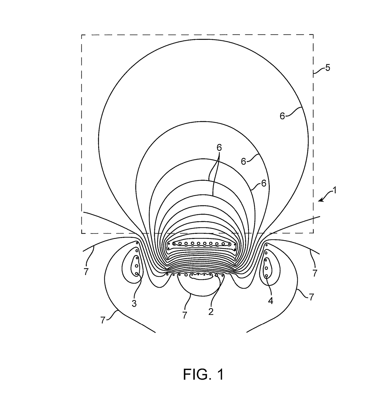
[0164]In this disclosure new ferrite-less structures are proposed that can be non-polarised magnetic flux structures, or developed to cre...


PUM


Abstract

Inductive power transfer flux coupling apparatus includes a first coil arranged in a first layer and configured to generate or receive a magnetic coupling flux in a flux coupling region, and a second coil. At least part of the second coil being arranged in a second layer and is configured to generate a magnetic flux that reflects flux from the first coil,

Description

FIELD OF THE INVENTION[0001]The invention relates to apparatus for producing magnetic flux from a source of electrical energy or receiving magnetic flux to provide a source of electrical energy. In one application the invention provides a flux coupling structure for inductive power transfer (IPT) i.e. wireless power transfer applications. Such applications may include static and dynamic electric vehicle charging, and low power applications such as charging mobile communications devices.BACKGROUND[0002]IPT systems are discussed generally and in particular in connection with a powered roadway application in published international patent publication WO 2011 / 016736. In the system described in that publication, a pad to pad IPT transmission method is used. The pads include a magnetically permeable material such as ferrite in both the transmitter and receiver pad in order to keep the size of those devices as small as possible whilst still transferring the required power. Specific constru...

Claims


Application Information

Patent Timeline
IPC IPC(8): H02J50/70H02J50/40H02J50/60H02J7/02H01F38/14H01F27/28B60L11/18H02J50/12H02J50/90
CPCH02J50/70H02J50/12H02J50/40H02J50/60H02J50/90B60L2270/147H01F27/2804B60L11/182H02J7/025H01F2027/2809H01F38/14H01F27/346Y02T10/7072Y02T90/14H02J50/005B60L53/122B60L53/126B60L53/124Y02T10/70H02J50/402Y02T90/12
Inventor BOYS, JOHN TALBOTCOVIC, GRANT ANTHONYMARQUEZ, ABIEZER TEJEDAPEARCE, MATTHEWGAWITH, JAMES DUNCAN DEANS
Owner AUCKLAND UNISERVICES LTD
Why Eureka
Try Eureka