
Method and Apparatus for Characterization and Compensation of Optical Impairments in InP-Based Optical Transmitter

a technology of optical transmitters and optical impairments, applied in the field of optical impairment characterization and compensation of optical impairments in inp-based optical transmitters, can solve the problems of low drive voltage, low form factor of high-capacity systems, and low component reliability of linbosub>3/sub>modulators, etc., to achieve low drive voltage. the effect of low drive voltag

Active Publication Date: 2017-08-03
II VI DELAWARE INC
View PDF0 Cites 7 Cited by
  • Summary
  • Abstract
  • Description
  • Claims
  • Application Information

AI Technical Summary

Benefits of technology

[0002]The ever increasing demand for optical fiber communication capacity continues to drive improvements in optical transmitter technology used in long-haul and metro optical network deployments. The need to address the combination of large bandwidth requirements, high port density, and lower system power consumption continue to push technology limits. In-Phase Quadrature-Phase (IQ) optical modulators support the high modulation bandwidths in today's coherent optical systems. Important modulator performance parameters for this application include low drive voltage to produce a phase shift of π-radians, Vπ, high linearity, high modulation bandwidth, and low insertion loss. In addition, high-capacity systems demand a small form factor and high component reliability.
[0003]Current generation IQ modulators rely heavily on lithium niobate LiNbO3 technology. However, LiNbO3 modulators have fundamental limitations on the modulator size needed to achieve low drive voltages. Compound III-V semiconductor-based modulator technologies have the potential for high bandwidth and compact device configurations, and III-V devices are already widely used as optical laser sources and detectors in currently deployed telecommunications systems. Indium phosphide (InP) technology, in particular, is well suited for modulating telecommunication system wavelengths. Indium phosphide technology is also compatible with wafer-scale fabrication that allows precise process controls and can be used with low cost packaging. These features of indium phosphide technology have dramatically reduced the cost of InP modulator components, enabling InP modulators to have an acceptable cost per transmitted bit.

Problems solved by technology

In addition, high-capacity systems demand a small form factor and high component reliability.
However, LiNbO3 modulators have fundamental limitations on the modulator size needed to achieve low drive voltages.

Method used


Image

  • Method and Apparatus for Characterization and Compensation of Optical Impairments in InP-Based Optical Transmitter
  • Method and Apparatus for Characterization and Compensation of Optical Impairments in InP-Based Optical Transmitter
  • Method and Apparatus for Characterization and Compensation of Optical Impairments in InP-Based Optical Transmitter

Examples


Embodiment Construction

[0016]Reference in the specification to “one embodiment” or “an embodiment” means that a particular feature, structure, or characteristic described in connection with the embodiment is included in at least one embodiment of the teaching. The appearances of the phrase “in one embodiment” in various places in the specification are not necessarily all referring to the same embodiment.

[0017]It should be understood that the individual steps of the methods of the present teachings may be performed in any order and / or simultaneously as long as the teaching remains operable. Furthermore, it should be understood that the apparatus and methods of the present teachings can include any number or all of the described embodiments as long as the teaching remains operable.

[0018]The present teaching will now be described in more detail with reference to exemplary embodiments thereof as shown in the accompanying drawings. While the present teachings are described in conjunction with various embodimen...


PUM


Abstract

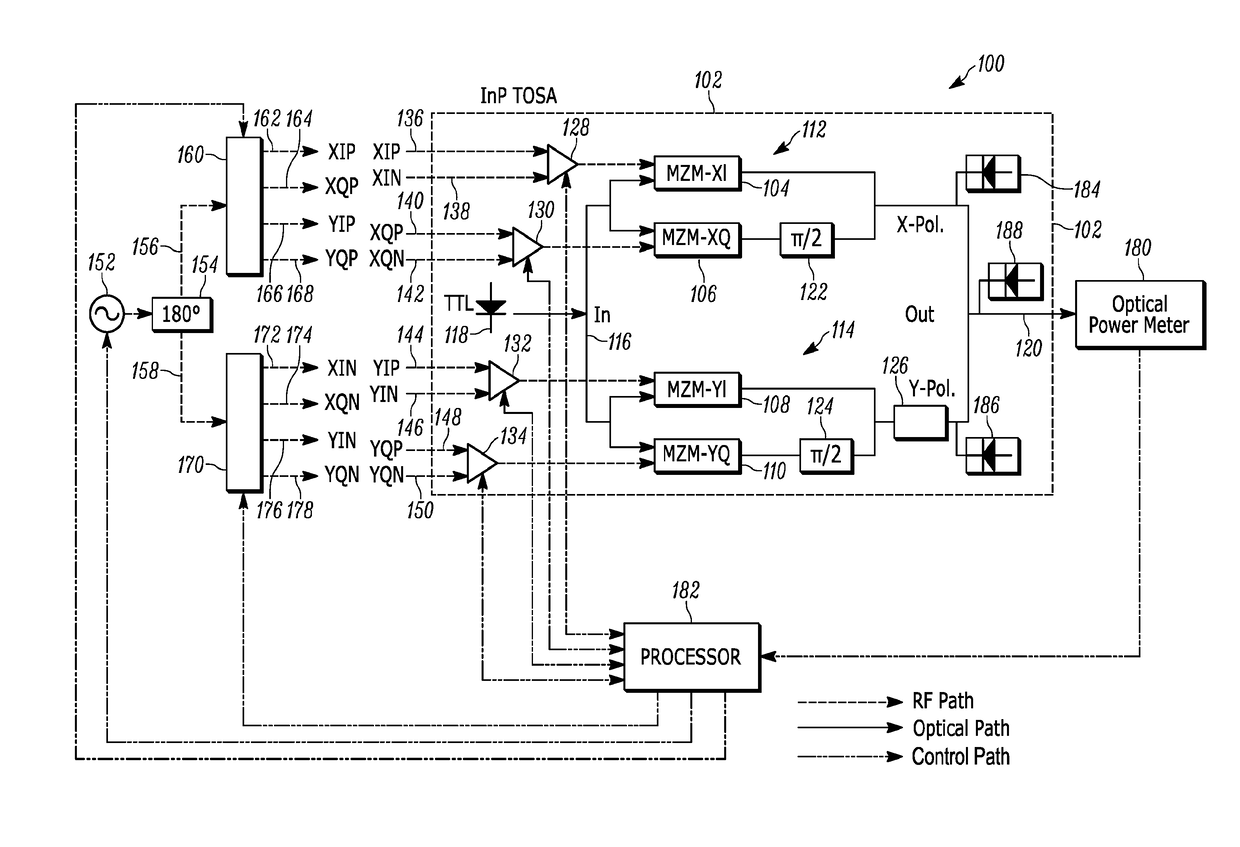
A method and apparatus for characterizing and compensating optical impairments in an optical transmitter includes operating an optical transmitter comprising a first and second parent MZ, each comprising a plurality of child MZ modulators that are biased at respective initial operating points. An electro-optic RF transfer function is generated for each of the plurality of child MZ modulators. Curve fitting parameters are determined for each of the plurality of electro-optic RF transfer functions and operating points of each child MZ modulator are determined using the curve fitting parameters. An IQ power imbalance is determined using the curve fitting parameters. Initial RF drive power levels are determined that compensate for the determined IQ power imbalance. The XY power imbalance is determined for initial RF drive power levels using the curve fitting parameters. The operating RF drive powers are determined that at least partially compensate for the first and second IQ power imbalances and for the XY power imbalance for the optical transmitter.

Description

[0001]The section headings used herein are for organizational purposes only and should not to be construed as limiting the subject matter described in the present application in any way.INTRODUCTION[0002]The ever increasing demand for optical fiber communication capacity continues to drive improvements in optical transmitter technology used in long-haul and metro optical network deployments. The need to address the combination of large bandwidth requirements, high port density, and lower system power consumption continue to push technology limits. In-Phase Quadrature-Phase (IQ) optical modulators support the high modulation bandwidths in today's coherent optical systems. Important modulator performance parameters for this application include low drive voltage to produce a phase shift of π-radians, Vπ, high linearity, high modulation bandwidth, and low insertion loss. In addition, high-capacity systems demand a small form factor and high component reliability.[0003]Current generation...

Claims


Application Information

Patent Timeline
Patent Type & Authority Applications(United States)
IPC IPC(8): H04B10/54H04B10/508
CPCH04B10/54H04B10/508H04B10/516H04B10/588H04B10/07955H04B10/564H04B10/5053H04B10/50572H04B10/58
Inventor BHANDARE, SUHAS P.EREIFEJ, HEIDER N.KHALOUF, IHAB E.COLYAR, MARK
Owner II VI DELAWARE INC
Learn More