Waterproof type control apparatus

a control apparatus and water-repellent technology, applied in the direction of electrical apparatus casings/cabinets/drawers, casings/cabinets/drawers details, coupling device connections, etc., can solve the problems of heat generated in the casing not being transmitted and dissipated, the structure becomes complicated and expensive, and the mounting structure of the water-repellent filter becomes simple and cheaper, and the effect of reducing the air pressure differen

a control apparatus and water-repellent technology, applied in the direction of electrical apparatus casings/cabinets/drawers, casings/cabinets/drawers details, coupling device connections, etc., can solve the problems of heat generated in the casing not being transmitted and dissipated, the structure becomes complicated and expensive, and the mounting structure of the water-repellent filter becomes simple and cheaper, and the effect of reducing the air pressure differen

US20170223847A1Active Publication Date: 2017-08-03MITSUBISHI ELECTRIC CORP +1

Image

  • Waterproof type control apparatus
  • Waterproof type control apparatus
  • Waterproof type control apparatus

Examples


embodiment 1

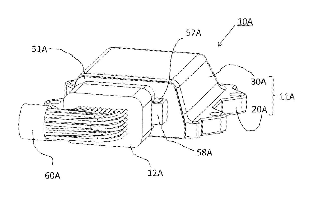
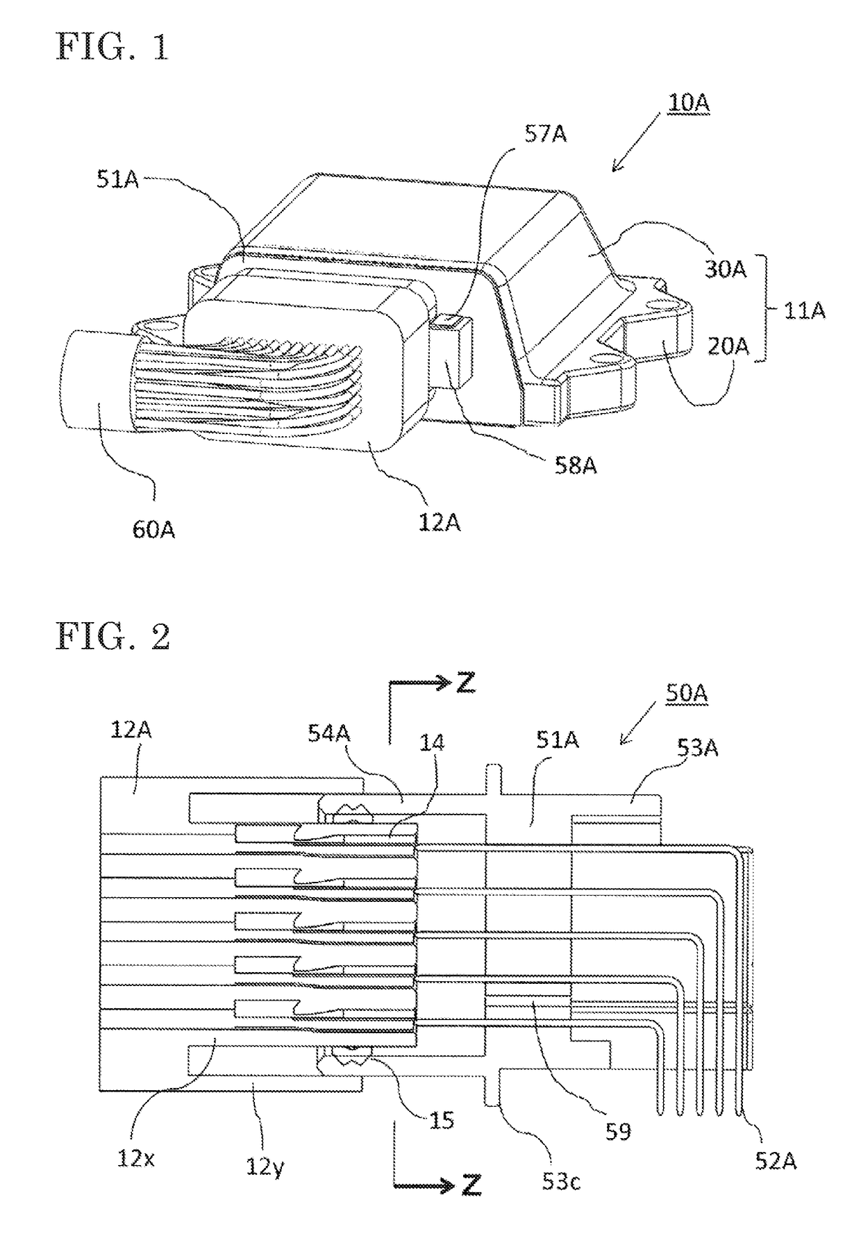
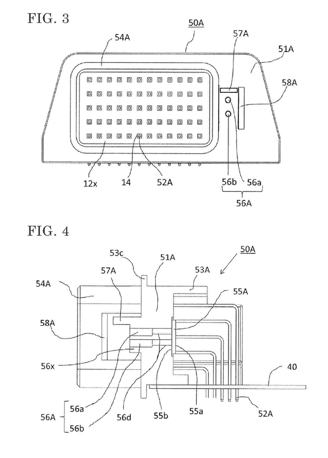
[0044](1) Detailed Description of Configuration FIG. 1 is an external view of a waterproof type control apparatus according to Embodiment 1, FIG. 2 is a cross-sectional view of a connector connection portion in FIG. 1, FIG. 3 is a cross-sectional view taken along a Z-Z line in FIG. 2, FIG. 4 is a detailed cross-sectional view of a connector housing in FIG. 1, FIGS. 5A to 5D are front views showing modifications of a poured water blocking wall in FIG. 3, and FIG. 6 is a front view of an atmospheric opening in FIG. 4. Hereinafter, the configurations of these drawings will be sequentially described in detail.

[0045]In FIG. 1, a casing 11A includes: a base 20A that has mounting legs at four sides thereof and is made of an aluminum die casting or a sheet metal; and a cover 30A that is made of a resin or a sheet metal, a circuit board 40 on which a connector housing 50A described later with reference to FIG. 4 is mounted is sealed and housed in the casing 11A, and an outer portion from a p...

embodiment 2

(1) Detailed Description of Configuration and Effects / Operation

[0133]FIG. 9 is an external view of a waterproof type control apparatus according to Embodiment 2 of the present invention, FIG. 10 is a plan view of a connector connection portion in FIG. 9, FIG. 11 is a detailed cross-sectional view of a connector housing in FIG. 9, FIG. 12A is a detailed cross-sectional view of a modification of the connector housing in FIG. 9, and a FIG. 12B is a cross-sectional view taken along a Y-Y line in FIG. 12A.

[0134]Hereinafter, the difference from FIGS. 1 to 8 of Embodiment 1 will be mainly described in detail. In each drawing, the same reference numerals denote the same or equivalent portions.

[0135]The main difference from Embodiment 1 is that an outer annular peripheral wall 54B or 54C of a connector housing 50B or 50C is divided into first and second annular peripheral walls 54a and 54b and first and second groups of first connection terminals 52a and 52b are pressed-fitted and held by a ...


PUM


Abstract

A circuit board is sealed and housed in a casing including a base and a cover, a connector housing including a partition wall is mounted on the circuit board, and an electrical connection between the interior and the exterior of the casing is established. A water-repellent filter is fixed to an inner surface of the partition wall, an outer surface portion of the water-repellent filter is opened to atmosphere via the breath ventilation hole, and an atmospheric opening surface thereof is formed such that the atmospheric opening surface being wetted directly with water is avoided by a poured water blocking wall and water barrier walls. A position where the poured water blocking wall is provided is changed by an insert mold in response to the direction of the mounting surface of the base.

Description

FIELD OF THE INVENTIONTechnical Field[0001]The present invention relates to a waterproof type control apparatus that is, for example, an on-vehicle electronic control apparatus provided in an engine room, and particularly relates to improvement in a breath ventilation structure in which a water-repellent filter is provided between the interior of a waterproof sealed casing having a heating component housed therein and outside air to protect a waterproof sealing structure.DESCRIPTION OF THE RELATED ARTBackground Art[0002]In a waterproof type control apparatus in which a circuit board is sealed and housed in a casing that includes a base and a cover, circuit components, including a heating component, and an external wiring connector housing exposed partially from the casing are mounted on the circuit board, and a waterproof sealing material is provided on a joined surface of the base, the cover, and the connector housing, a water-repellent filter is conventionally provided to the cove...

Claims


Application Information

Patent Timeline
03 Aug 2017
Publication
US20170223847A1
IPC
H05K5/02; H05K5/00; H05K5/03
CPC
H05K5/0213; H05K5/0069; H05K5/0247; H05K5/03; H01R13/5202; H01R13/5213; H01R13/5216; H01R13/5227
Inventors
NISHIDA, MITSUNORI; NISHIZAWA, OSAMU