Composite wing structure and methods of manufacture

a technology of wing structure and composite material, which is applied in the direction of vertical landing/take-off aircraft, spars/stringers, other domestic articles, etc., can solve the problems of tight tolerances, extremely time-consuming and laborious process, and complex assembly of torque box structure b>30/b>

Active Publication Date: 2017-08-10
BELL HELICOPTER TEXTRON INC
View PDF5 Cites 13 Cited by
  • Summary
  • Abstract
  • Description
  • Claims
  • Application Information

AI Technical Summary

Benefits of technology

[0014]In a first aspect, there is a method of manufacturing a tiltrotor wing structure including providing a spar mold having a plurality of bores extending from an exterior surface of the mold to an interior surface of the mold, the plurality of bores corresponding to a plurality of primary coordination holes in a spar member, the spar mold having an interior surface that resembles the desired outer contour of the spar and having a periphery defined by a top edge, a bottom edge and outboard ends; selecting a plurality of resin impregnated plies to ensure that the plies continuously extend beyond the periphery of the spar mold; laying the plurality of plies in the spar mold; compacting the plurality of plies in the spar mold; curing the plurality of plies in the spar mold to form a cured spar member that extends beyond the periphery of the spar mold; accurately drilling a plurality of primary coordination holes in the cured spar member in the spar mold using a tool positioned in the plurality of bores; removing the cured spar member from the spar mold; positioning the cured spar member in a numerically controlled machining assembly; locating a periphery of the cured spar member based on the location of the primary coordination holes by the numerically controlled machining assembly; and trimming at least at the periphery of the cured spar member based on the locating a periphery step by the numerically controlled machining assembly.

Problems solved by technology

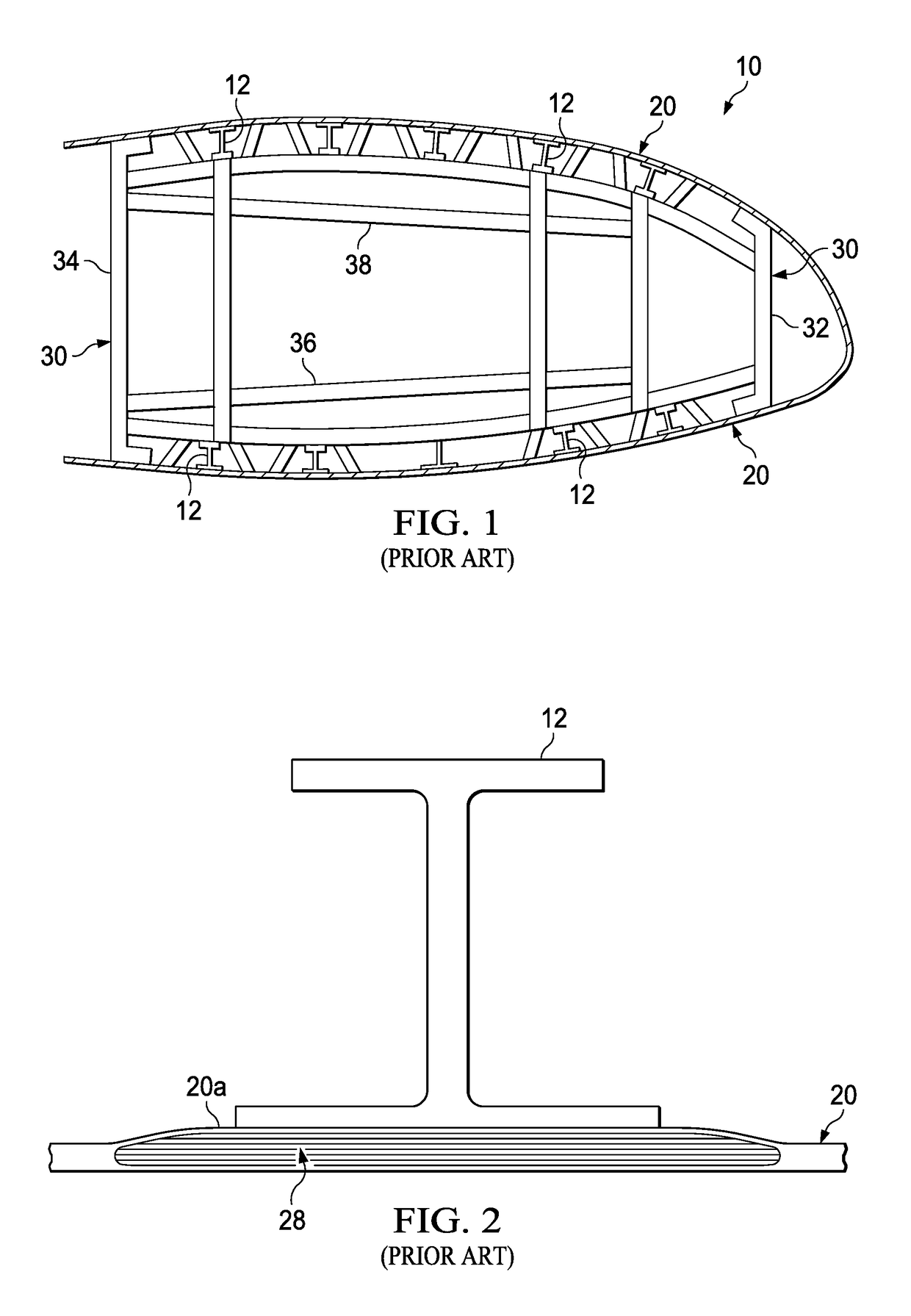
During manufacture of the skin 20 each of the reinforcement strips 28 is cut, labeled, and positioned in a mold, which is an extremely time-consuming and laborious process.
When the size and shape of a reinforcement strip 28 is used repeatedly, a problem results in that the reinforcement strips 28 are pre-cut and stored in a controlled atmosphere environment and must be identified and thawed by a user each time a reinforcement strip is needed for a composite.
The assembly of the torque box structure 30 is very complex, often with very tight tolerances required.
The installation of the fasteners to the skins 20 and other structural components is also difficult because there is limited access to small interior spaces and complicated sealing requirements.
Moreover, a large number of fasteners is required for each wing 10, which can cause the structures to warp and dimensional growth during assembly.
The assembly of the torque box 30 is time consuming and extremely labor intensive at each of the various stages of manufacture (manufacture of the composites, sub-assembly, installation stages).

Method used


Image

  • Composite wing structure and methods of manufacture
  • Composite wing structure and methods of manufacture
  • Composite wing structure and methods of manufacture

Examples


Embodiment Construction

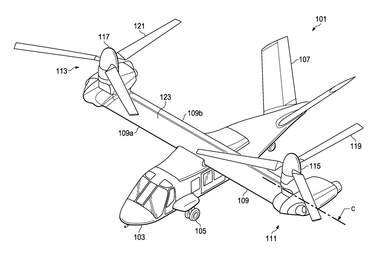
[0081]Illustrative embodiments of the apparatus and method are described below. In the interest of clarity, all features of an actual implementation may not be described in this specification. It will of course be appreciated that in the development of any such actual embodiment, numerous implementation-specific decisions must be made to achieve the developer's specific goals, such as compliance with system-related and business-related constraints, which will vary from one implementation to another. Moreover, it will be appreciated that such a development effort might be complex and time-consuming but would nevertheless be a routine undertaking for those of ordinary skill in the art having the benefit of this disclosure.

[0082]In the specification, reference may be made to the spatial relationships between various components and to the spatial orientation of various aspects of components as the devices are depicted in the attached drawings. However, as will be recognized by those ski...


PUM

PropertyMeasurementUnit
widthaaaaaaaaaa
widthaaaaaaaaaa
widthaaaaaaaaaa

Abstract

A method of manufacturing a tiltrotor wing structure including providing a spar mold having a plurality of bores extending from an exterior surface of the mold to an interior surface of the mold, the plurality of bores corresponding to a plurality of primary coordination holes in a spar member, the spar mold having a periphery defined by a top edge, a bottom edge and outboard ends; selecting a plurality of resin impregnated plies to ensure that the plies continuously extend beyond the periphery of the spar mold; laying the plies in the spar mold; curing the plies in the mold to form a cured spar member that extends beyond the periphery of the spar mold; and accurately drilling a plurality of primary coordination holes in the cured spar member in the spar mold using a tool positioned in the plurality of bores.

Description

CROSS-REFERENCE TO RELATED APPLICATIONS[0001]This patent application claims the benefit of the filing date of U.S. Provisional Patent Application No. 62 / 292,673, filed Feb. 8, 2016, which is hereby incorporated by reference.BACKGROUND[0002]Field of the Invention[0003]The present disclosure relates to a method for assembling a tiltrotor wing structure.[0004]Description of Related Art[0005]Modern aircraft are manufactured from a wide variety of materials, including steel, aluminum, and a wide variety of composite materials. Most structural components are made from strong, rigid materials. However, in order to conserve weight, the structural components are often made from a thin layer of metal or composite that includes reinforcement strips of material reinforced with stringers.[0006]Tiltrotor aircraft have complicated proprotor assemblies located at opposing wing tips that operate between a helicopter mode to take off, hover, fly, and land like a conventional helicopter; and an airpla...

Claims


Application Information

Patent Timeline
Patent Type & Authority Applications(United States)
IPC IPC(8): B64C3/26B64C29/00B64F5/00B64C3/18
CPCB64C3/26B64F5/00B64C29/0033B64C3/185B64C1/12B64C3/24B64F5/10B29L2031/3076B29C2793/009Y02T50/40B29C70/302B29C35/02B29C70/06B29C70/34B29C70/545B29D99/001B29L2031/3085B32B2250/05B32B2605/18B29C65/48B29D99/0089B32B3/12B32B7/12B32B2305/024
Inventor CARLSON, DAVID G.MCCULLOUGH, JOHN R.WOLFE, DOUGLAS K.DECKER, GEORGE R.STANNEY, KEITH A.
Owner BELL HELICOPTER TEXTRON INC
Why Eureka
Try Eureka