Serial communication link with optimal transfer latency

Active Publication Date: 2017-08-10
QUALCOMM INC
View PDF0 Cites 4 Cited by
  • Summary
  • Abstract
  • Description
  • Claims
  • Application Information

AI Technical Summary

Benefits of technology

This patent describes a method to reduce latency in serial transmissions by comparing frames and identifying which signals have changed their state. By doing this, the serial interface can decide to transmit a bit mode frame or a full-batch frame based on the number of changed bits. This results in quicker transmissions and reduced latency.

Problems solved by technology

Conversely, if a sufficient number of signals in the current frame have changed state compared to the previous frame, it no longer saves latency to transmit a bit-mode frame such that the full-batch mode frame is transmitted instead of the bit-mode.

Method used


Image

  • Serial communication link with optimal transfer latency
  • Serial communication link with optimal transfer latency
  • Serial communication link with optimal transfer latency

Examples


Embodiment Construction

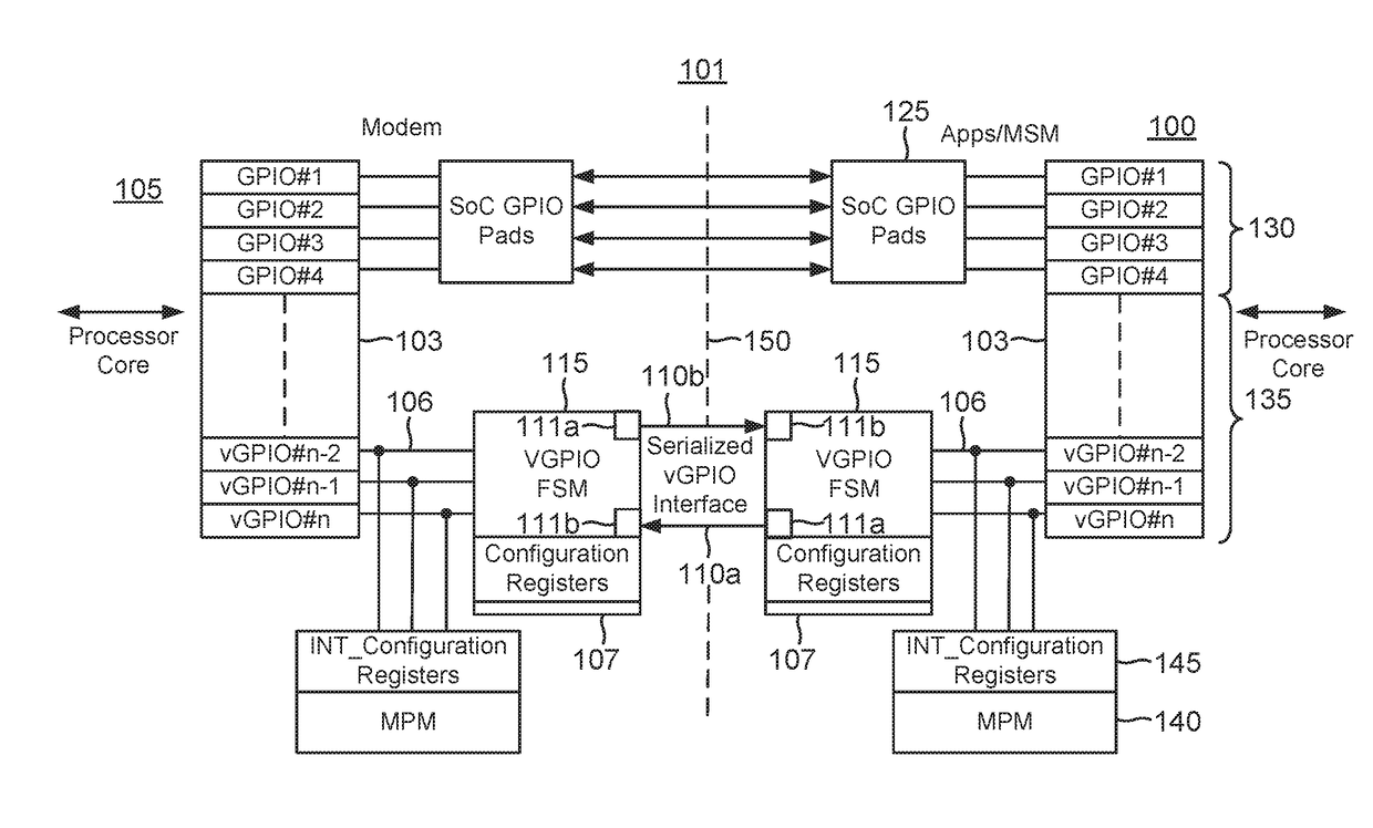
[0017]A serial interface is disclosed that serializes a plurality of signals into a frame in which each signal has its own unique position in the frame. For example, an eight-bit frame may be considered to be arranged from a first bit through an eighth bit. A first signal is defined through the binary value of the first bit, a second signal is defined through the binary value of the second bit, and so on such that a signal in a received frame may be identified through its position in the frame. In alternative embodiments, one or more of the signals may comprise a multi-bit signal. But such multi-bit signals are also assigned to unique positions within a frame.

[0018]Given such unique positioning within a frame, a receiver may identify a given signal within the frame by its unique position. For example, the first bit in an frame may be assigned to a first one-bit signal. Similarly, the second bit in a frame may be assigned to second one-bit signal, and so on such that the nth bit in a...


PUM


Abstract

A serial interface is provided with a finite state machine configured to compare a current state for a plurality of signals to a previous state to determine whether to transmit a frame including the plurality of signals or to transmit a frame that includes only a bit position of a changed one of the signals.

Description

TECHNICAL FIELD[0001]This application relates to serial communication, and more particularly to a serial communication link with optimal transfer latency.BACKGROUND[0002]Serial communication interfaces are a common element for an integrated circuit processor such as a system on a chip (SoC). An SoC must serve an ever expanding set of functions such as web browsing, email, video gaming, and so on. To interface with its various peripherals during the execution of these functions requires a certain number of pins or terminals. It would be convenient to assign each input / output signal to its own unique pin but increasing the number of pins for an integrated circuit increases its costs. Moreover, even if cost were no issue, an integrated circuit can only fit so many pins onto its surfaces.[0003]To limit the number of required pins, conventional SoCs typically include have one or more serial communication interfaces such as a universal asynchronous receiver transmitter (UART) interface, a...

Claims


Application Information

Patent Timeline
IPC IPC(8): G06F13/16G06F13/12G06F13/40G06F13/42G06F15/78
CPCG06F13/161G06F13/4291G06F13/126G06F13/4018G06F15/7817G06F13/4282
Inventor MISHRA, LALAN JEEWIETFELDT, RICHARD
Owner QUALCOMM INC
Why Eureka
Try Eureka