Magnetic resonance wireless power transmission device capable of adjusting resonance frequency

Active Publication Date: 2017-08-10
MAPS
View PDF8 Cites 17 Cited by
  • Summary
  • Abstract
  • Description
  • Claims
  • Application Information

AI Technical Summary

Benefits of technology

[0028]According to an exemplary embodiment, a resonant frequency can be electrically tuned. In other words, resonant frequencies are not regularized by adjusting a passive device, and the resonant frequency can be tuned with only an electric signal without tuning a passive device. Since resonant frequency tuning and power control are possible without changing a driving frequency fdrv, the present invention is suited to standards, such as alliance for wireless power (A4WP), and control is possible without a direct curren

Problems solved by technology

However, since the method of tuning passive devices involves physically tuning L and C, productivity is low, and it is not easy to cope with a case in which L and C values are changed due to an external factor.
However, when too much energy is transmitted, the voltage VRECT of the PRU 12 increases excessively and destroys the rectifier 130 and the DC-DC converter 140, and when too little energ

Method used


Image

  • Magnetic resonance wireless power transmission device capable of adjusting resonance frequency
  • Magnetic resonance wireless power transmission device capable of adjusting resonance frequency
  • Magnetic resonance wireless power transmission device capable of adjusting resonance frequency

Examples


Embodiment Construction

[0054]Hereinafter, exemplary embodiments of the present invention will be described in detail with reference to the accompanying drawings. In the following description of the present invention, a detailed description of a known art related to the present invention will be omitted when determined to unnecessarily obscure the subject matter of the present invention. Also, the terms used in the following description are terms defined in consideration of functions in the exemplary embodiments of the present invention and may vary depending on a user's or an operator's intention, practice, or so on. Therefore, definitions of terms used herein should be made based on the content throughout the specification.

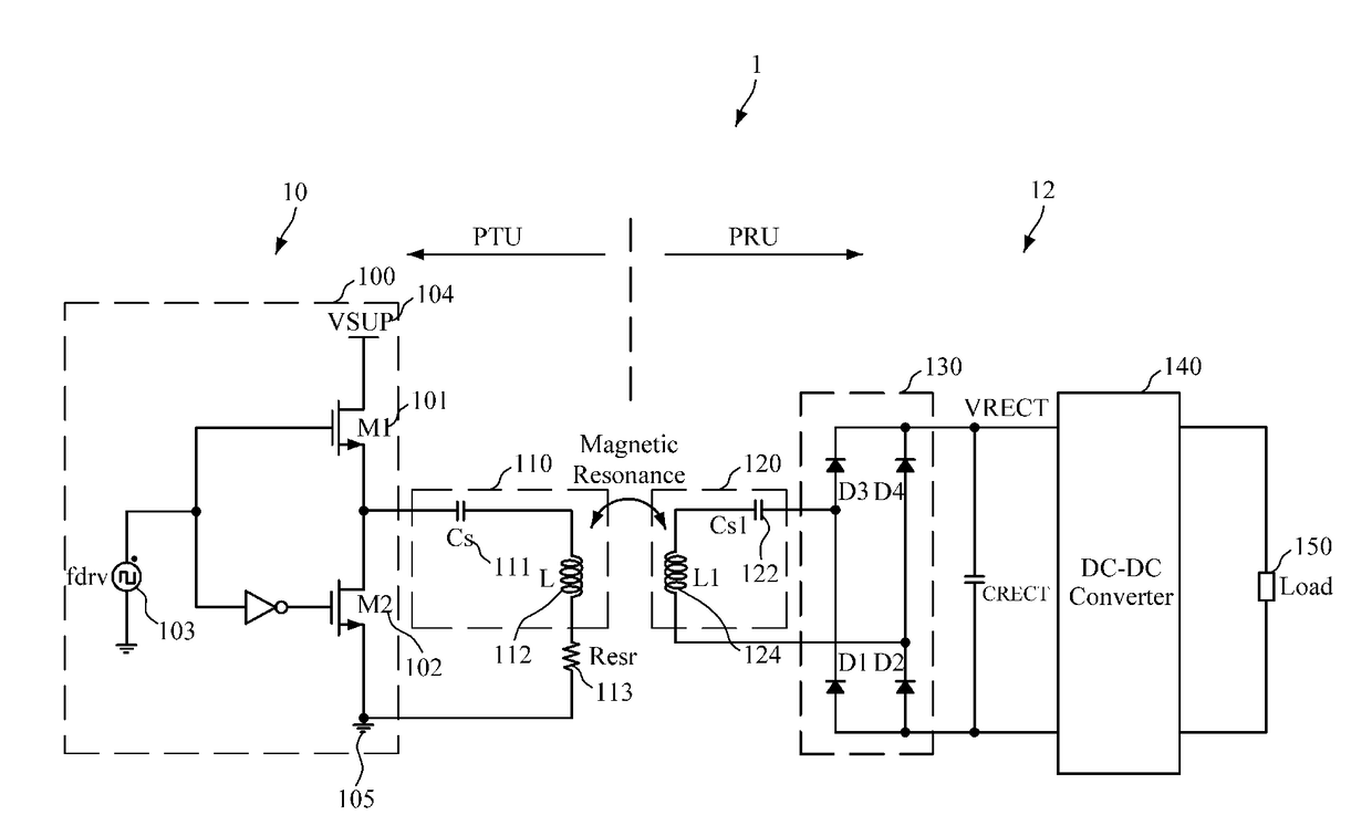
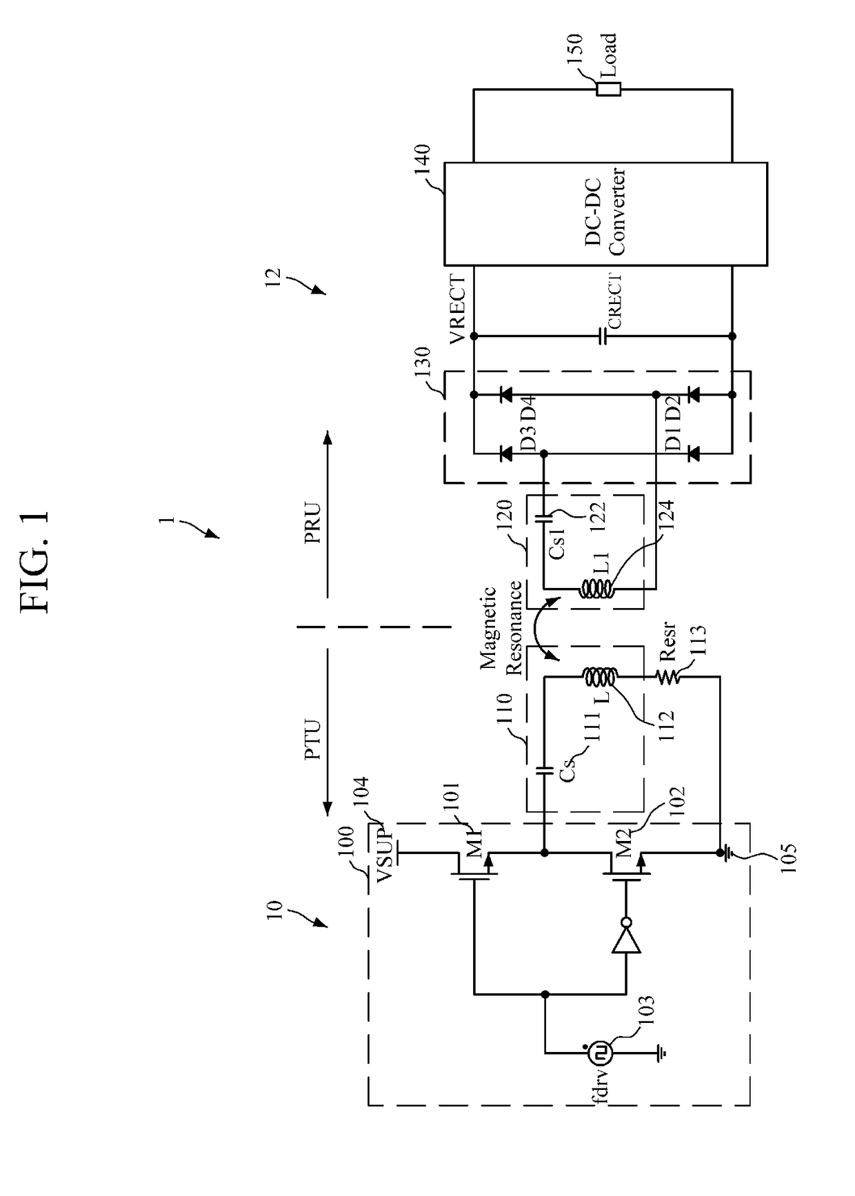
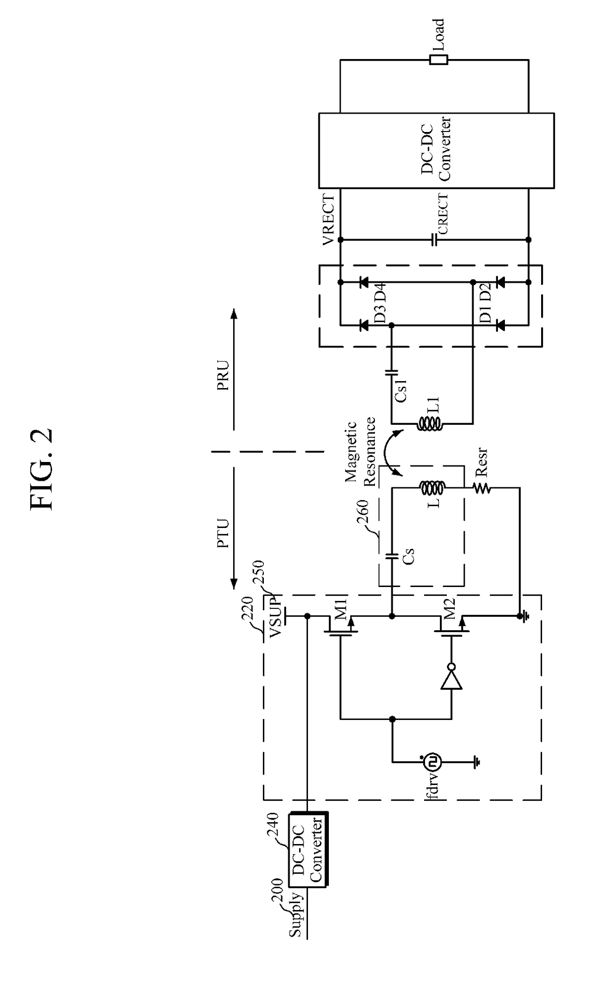
[0055]A wireless power transmission system of the present invention tunes a resonant frequency using an active resonant frequency tuning method. To tune the resonant frequency, a duty ratio is controlled using a frequency component applied to a resonator or a frequency component genera...


PUM


Abstract

A magnetic resonance wireless power transmission device capable of adjusting resonance frequency is disclosed. A wireless power transmission device according to an embodiment of the present invention comprises: a power amplifier for amplifying a wireless power signal using a driving frequency signal; a resonator for configuring a resonance tank and wirelessly transmitting, through magnetic resonance, the wireless power signal output from the power amplifier using a resonance frequency of the resonance tank; and a resonance control unit for controlling a duty ratio using a frequency applied to the resonator or a frequency signal generated by the resonator and adjusting the resonance frequency of the resonator.

Description

TECHNICAL FIELD[0001]The present invention relates to a wireless power transmission technology, and more particularly, to a wireless power transmission technology using magnetic resonance.BACKGROUND ART[0002]FIG. 1 is a configuration diagram of a general magnetic resonance wireless power transmission system.[0003]Referring to FIG. 1, a magnetic resonance wireless power transmission system 1 includes a power transmitting unit (PTU) 10 that supplies a power signal through magnetic resonance and a power receiving unit (PRU) 12 that receives the power signal from the PTU 10.[0004]The PTU 10 includes a power amplifier 100 and a resonator 110. The power amplifier 100 includes N-channel metal oxide semiconductors (NMOSs) M1101 and M2102, and the resonator 110 includes a transistor (Cs) 111 and an inductor (L) 112. In FIG. 1, the power amplifier 100 is limited to class-D, but may be replaced by a class-AB or class-B power amplifier. The power amplifier is operated at a driving frequency (fd...

Claims


Application Information

Patent Timeline
IPC IPC(8): H02J50/12H03F3/217
CPCH02J50/12H03F2200/243H03F3/2173H03F3/3015H03F3/45475H03F2200/541H03F2203/45512H03F2203/45528H03F2203/45594H03F2203/45604H03F2200/391Y02E60/00H02J50/80H03H3/0077H04B5/0037H04B5/0075H03H2003/0414Y04S40/121
Inventor HWANG, JONG-TAESHIN, HYUN-ICKLEE, DONG-SULEE, JONG-HOONJEON, SANG-OSONG, IK-GYOOKIM, DAE-HORHEE, JOON
Owner MAPS
Why Eureka
Try Eureka