High-speed screening apparatus for a raman analysis-based high-speed multiple drug

a screening apparatus and high-speed technology, applied in the field oframan analysis-based screening apparatuses for multiple drugs, can solve the problems of reducing the laboratory space necessary for instruments, disadvantageous in space, time and finances, and time taken, and achieves strong surface-enhanced raman scattering signals, high speed, and high reproducibility

Inactive Publication Date: 2014-04-24
KOREA RES INST OF CHEM TECH
View PDF9 Cites 11 Cited by
  • Summary
  • Abstract
  • Description
  • Claims
  • Application Information

AI Technical Summary

Benefits of technology

[0029]As described hitherto, the screening apparatus and method of the present invention is not designed to detect autofluorescence, but to measure Raman signals generated from core-gap-shell nanoparticles, so that it exhibits no interference between fluorescent labels. The core-gap-shell nanoparticles show very strong surface-enhanced Raman scattering (SERS) signals, with an SERS enhancement factor of up to about 1012, and are proven to be highly reproducible. In addition, the use of a CCD camera as a detector allows the apparatus and method of the present invention to screen multiple drugs at a high speed because the CCD camera, which operates in a non-scanning manner, can photograph individual wells of well plates momentarily and can take pictures of other wells in association with the operation of the motion controller. Further, the apparatus and method of the present invention can code multiple colors for Raman images, and are effectively applicable to the screening of various drugs.

Problems solved by technology

A great expense for this screening process has given rise to making every effort to design effective screening methods and develop high-speed and minimized apparatuses and reagents which allow the screening of as many compounds as possible within a short period of time.
(1) Rapidity: Given a higher screening speed, an HTS can screen a higher number of compounds, and thus can complete its performance within a shorter time and at a lower expense.
(2) Expense: Reagents used in the screening process account for a large portion of the total screening expense. A measure must be taken toward financial retrenchment.
(3) Miniaturization: Miniaturization is not only one of the best measures to cut expenses for reagents, but can also reduce the time taken to perform a screening process. Besides, it can reduce laboratory space necessary for the instruments.
(4) Automation: Automation increases reproducibility of results as well as the speed of screening. Particularly, it makes a great contribution to the reduction of experimental error.
(5) Screening sensitivity: The sensitivity of a detection method is directly relevant to the quantity of samples to be used. High detection sensitivity is required because it takes a longer time to screen samples of lower sensitivity.
(6) Non-radioactive method: As high as 50% of the HTS methodologies developed thus far use radioactive substances. However, radioactive substances produce waste which must be specifically cared for, and thus are disadvantageous in terms of space, time and finances.
(7) Simplicity: Because a method operating with filtration, separation, washing, distinction, and solid-state extraction requires additional expense and processes, the screening process should be simplified in a liquid state as much as possible.
The difference of yield between the primary and secondary screening processes incurs a significant bottleneck phenomenon in the development of new drugs.
Hence, it is an important challenge throughout new drug development to increase the efficiency of secondary screening to a level in harmony with the primary screening process without deteriorating the quality of data generated in the secondary screening.
However, fluorescent labels used in fluorescence assay weaken in fluorescence intensity (photobleaching), and exhibit interference between different fluorescent labels because excitation light with a very narrow wavelength range is used while the fluorescent light has a very broad range of wavelengths.
In addition, there are an extremely limited number of available fluorescent substances.
Due to low signal intensity, however, the stage of development of Raman spectroscopy has not yet reached the level where it can be used in practice in spite of research spanning a long period of time.
However, there have been almost no advances in preparing single molecule SERS active substrates based on the salt-induced aggregation of silver (Ag) nanoparticles having Raman active molecules (e.g., Rhodamine 6G) since the first study.
Like this, randomly roughened surfaces provide a multitude of interesting essential data associated with SERS, but this strategy is fundamentally impossible to reproduce because even a small change in surface morphology leads to a significant change of enhancement.

Method used


Image

  • High-speed screening apparatus for a raman analysis-based high-speed multiple drug
  • High-speed screening apparatus for a raman analysis-based high-speed multiple drug
  • High-speed screening apparatus for a raman analysis-based high-speed multiple drug

Examples


synthesis examples 1 to 3

Synthesis of Core-Gap-Shell Nanoparticles

[0104]A DNA strand was used as a Raman-dye modification platform with highly accurate position-controlling capability to synthesize an NNP (nanobridged nanogap particle) with a nanobridge-supported interior gap, as follows.

[0105]DNA-modified gold nanoparticles (20 nm in diameter; DNA sequences: [3′-HS—(CH2)3-(Dabcyl)-A10-PEG18-AAACTCTTTGCGCAC-5′] for Synthesis Example 1, [3′-HS—(CH2)3-(Cy3)-A10-PEG18-AAACTCTTTGCGCAC-5′] for Synthesis Example 2, and [3′-HS—(CH2)3-(TAMRA)-A10-PEG18-AAACTCTTTGCGCAC-5′] for Synthesis Example 3) were prepared according to literature procedures (S. J. Hurst, A. K. R. Lytton-Jean, C. A. Mirkin, Anal. Chem. 78, 8313 (2006)). To form gold shells around these DNA-modified gold nanoparticle cores, DNA-modified gold nanoparticles in a phosphate-buffered solution (0.3 M NaCl, 10 mM PB, pH 7.4) were reacted with a gold precursor (HAuCl4, a reductant (NH2OH—HCl) and 1% poly-N-vinyl-2-pyrrolidone (PVP; MW 40,000), followed b...

synthesis examples 4 to 6

Synthesis of PEG-Coated Core-Gap-Shell Nanoparticles

[0107]PEG was applied to the shell surface of each of the nanoparticles synthesized in Synthesis Examples 1 to 3 so as to render the particles well-dispersible in a cell culture media and thus more suitable for use in cellular experiments (“Dabcyl” (Synthesis Example 4), “Cy3” (Synthesis Example 5), “TAMRA” (Synthesis Example 6); refer to FIG. 9).

[0108]mPEG-SH (MW ˜5 kDa) was applied to the shell surface of the nanoparticles to prepare PEG-coated gold-silver core-shell nanoparticles (Synthesis Examples 4 to 6) with reference to ‘W. Peter Wuelfing, Stephen M. Gross, Deon T. Miles, and Royce W. Murray, J. Am. Chem. Soc. 120, 12696 (1998)’.

experimental example 1

Evaluation of Surface-Enhanced Raman Scattering Spectrum

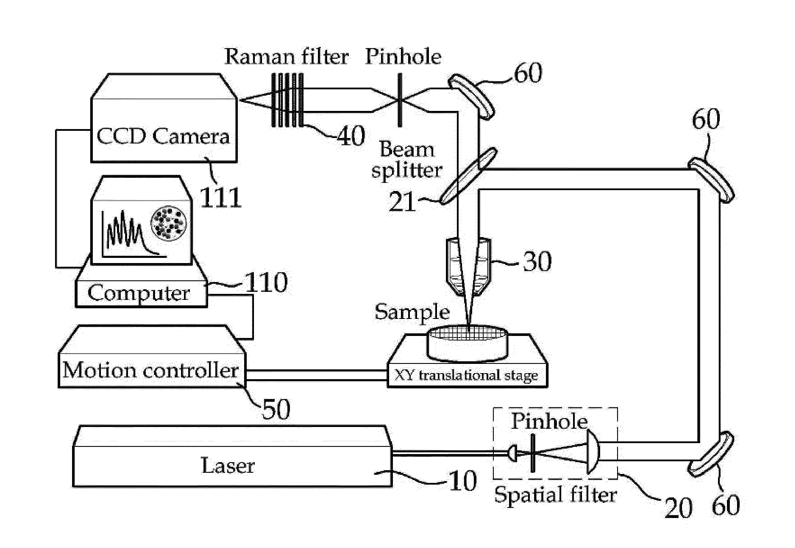
[0109]SERS spectra were recorded by the apparatus of the present invention, that is, the in-house nano-Raman spectroscope equipped with an inverted optical microscope (Axiovert 200, Zeiss) using the nanoparticles synthesized in Synthesis Examples 1 to 3.

[0110]First, 20 μL of each of the solutions containing the nanoparticles of Synthesis Examples 1 to 3 was applied to a cover glass slip by spin coating to construct a sample for spectral measurement. An excitation laser beam with a wavelength of 660 nm was directed at an energy of from 50 nW to 1 mW into an oil-immersion microscope objective (×100, 1.3 numerical aperture; ×50, 0.5 numerical aperture; Zeiss), which focuses the beam into the sample to generate Raman signals. The background Raman signals were collected on a liquid-nitrogen-cooled (−125° C.) CCD (charge-coupled device). All of the data was baseline-corrected to afford SERS spectra. The results are shown in FIG. 5.

[0...


PUM

PropertyMeasurementUnit
wavelengthaaaaaaaaaa
diameteraaaaaaaaaa

Abstract

The present invention relates to a high-speed screening apparatus for a Raman analysis-based high-speed multiple drug. The screening apparatus according to the present invention may easily detect a Raman signal using a core-cap-shell nanoparticle which amplifies the Raman signal by 1012 times and has high reproducibility through Raman spectroscopy in which materials do not interfere with each other and a spectrum has a sharp peak to detect the Raman signal multiple times. Also, since a CCD camera, not a scanner, may be used as the detector, the screening apparatus may multiply screen the drug at a high speed without movement between molecules within a sample. In addition, since multicolors of 5 colors or more may be coated, the screening apparatus may be usefully used for screening various drugs.

Description

TECHNICAL FIELD[0001]The present invention relates to a Raman analysis-based apparatus for screening multiple drugs at a high speed.BACKGROUND ART[0002]Drug development is an advanced country-type strategic process requiring a massive commitment of time and money of more than ten years and eight hundred million dollars, respectively. A well-developed social infrastructure is also necessary for drug development.[0003]Broadly, the process of drug development can be divided into the discovery of a drug target by basic research, the selection of effective and lead materials by compound screening, the determination of a candidate drug, clinical research through pre-clinical work / clinical phase 1, and commercialization through clinical phases 2 and 3.[0004]Of a total of 35,000 genes discovered thus far as drug targets, approximately 500 are currently under research for drug development, with a steady expansion of the development subject since the Human Genome Project. Once a drug target i...

Claims


Application Information

Patent Timeline
Patent Type & Authority Applications(United States)
IPC IPC(8): G01N33/58G02B21/36G01N21/65H04N5/372
CPCG01N33/587H04N5/372G02B21/367G01N21/658G01N33/15G01N21/65H04N25/71
Inventor SUH, YUNG DOUGJEON, KI SEOKKIM, HYUNG MINLEE, KANG TAEKJIN, SEUNG MINNAM, SANG HWANBAE, YUN MILEE, HAEMILEE, KYUNGHEEPARK, HYO SUNKIM, PHIL HWAN
Owner KOREA RES INST OF CHEM TECH
Why Eureka
Try Eureka