Systems and methods for transient-pressure testing of water injection wells to determine reservoir damages

Active Publication Date: 2017-08-17
SAUDI ARABIAN OIL CO
View PDF3 Cites 15 Cited by
  • Summary
  • Abstract
  • Description
  • Claims
  • Application Information

AI Technical Summary

Benefits of technology

[0011]In some embodiments, well test data obtained via a transient-pressure test operation can be used to determine various characteristics of the well and the reservoir, such as the following: a wellbore storage constant (C); a well skin factor (s); a fracture storage constant (Cf); a radial location of shallow damage (rd) indicative of the location of shallow damage; a shallow damage skin factor (sd) indicative of a severity of the shallow damage; a first permeability value (k1) indicative of permeability of the formation (e.g., in the radial direction) in a first region that is inside of the location of the radial location of shallow damage (rd); and a second permeability value (k2) indicative of permeability of the formation (e.g., in the radial direction) in a second region that is outside of the location of the radial location of shallow damage (rd). In some embodiments, the determinations can be based on an iterative analysis to determine a “matched” model for the well, including iteratively estimating a set of parameter values for the well (e.g., including values for some or all of the above characteristics) and identifying a model that generates a model prediction (or similar model data) that aligns with, or matches, the observed well test data for the well. Accordingly, the analysis may consider two skin factors; one adjacent to the wellbore (e.g., a well skin factor (s) just in the vicinity of the wall) and one at a shallow depth/radius from the wellbore (e.g., a shallow damage skin factor (sd)). Such a transient-pressure test operation and corresponding analysis of well test data obtained via such a reduced-pressure transient-pressure test operation for a well, may provide a complete characterization of the storage of the well due to induced fractures, as well as an identification of the location and the severity of shallow damage of the well. Such information can be used in the selection of one or more appropriate stimulation operations that can be employed to target and remediate the damage, thereby helping to restore the injection performance of the well.
[0012]Provided in some embodiments is an oil reservoir water injection well system, comprising a pump system adapted to inject water into the wellbore a wellbore of a well extending into an oil reservoir, a flow control system adapted to regulate flow of water in the wellbore, a flowmeter system adapted to measure fluid flow in the wellbore, a pressure gauge system adapted to measure fluid pressure in the wellbore, and a surface control unit. The surface control unit adapted to determine whether a minimum injection rate is s

Problems solved by technology

Applicants have recognized that damages in the formation of a reservoir can distort the results of transient-pressure tests (also referred to as “well tests”), and that the damages can be difficult to remediate, especially when they are not located at or near the wellbore.
With regard to distortion of the results of well tests, Applicants have recognized that the induced fractures can create a phenomenon where the well test data is devoid of a reservoir signature, making it difficult to extract well and reservoir characteristics from the well test data.
Where induced fractures are present, the induced fractures can accumulate substantial volumes of water during an active injection operation, but the induced fractures may close as the pressure decreases, forcing the accumulated water out of the fractures.
While this phenomenon is in progress, the pressure versus time data captured from the well during the fall-off period can be significantly distorted, indicating a relati

Method used


Image

  • Systems and methods for transient-pressure testing of water injection wells to determine reservoir damages
  • Systems and methods for transient-pressure testing of water injection wells to determine reservoir damages
  • Systems and methods for transient-pressure testing of water injection wells to determine reservoir damages

Examples


Embodiment Construction

[0030]The present invention will now be described more fully hereinafter with reference to the accompanying drawings in which example embodiments of the invention are shown. This invention may, however, be embodied in many different forms and should not be construed as limited to the illustrated embodiments set forth herein, rather, these example embodiments are provided so that this disclosure will be thorough and complete, and will fully convey the scope of the invention to those skilled in the art.

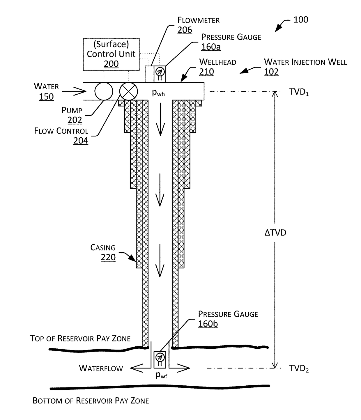
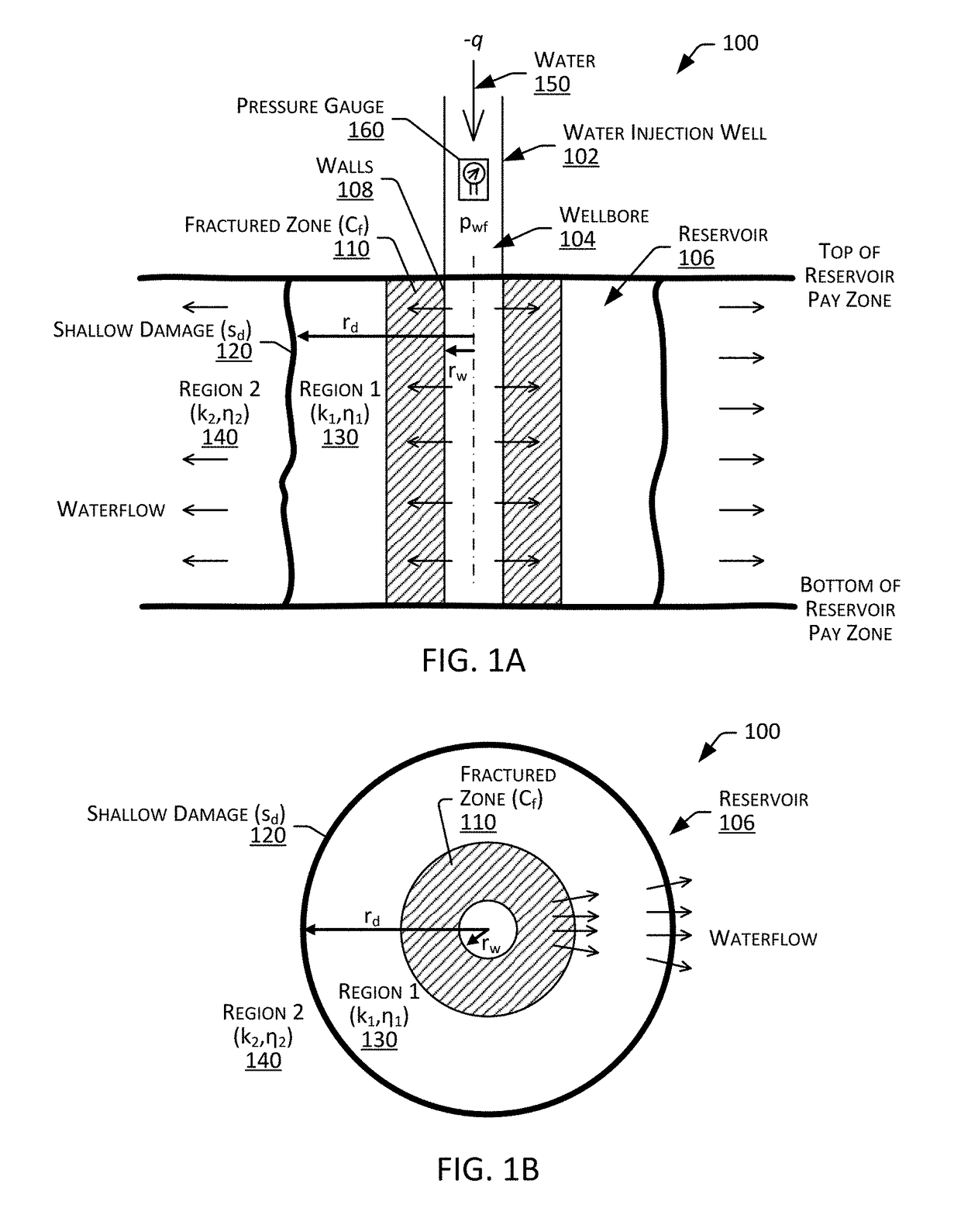
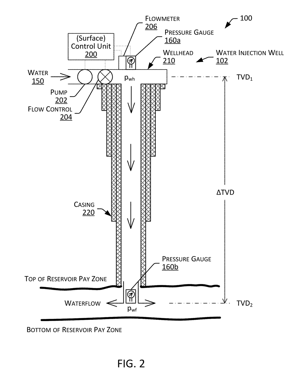
[0031]Described herein are systems and methods for transient-pressure testing of injection wells to determine damages in a reservoir. For example, embodiments describe a transient-pressure test operation (also known as a well test) for a water injection well of an oil reservoir to acquire corresponding well test data, and analytical solutions for determining various characteristics of the well and the reservoir, including the location and the severity of shallow damages in the reservoir...


PUM


Abstract

Provided in some embodiments are systems and methods for transient-pressure test of an oil reservoir water injection well system. Embodiments provide for determining a fracturing injection rate for the well, setting a test injection rate preferably below the fracturing injection rate, conducting a stabilized injection of water into a wellbore of the well at the test injection rate for a prescribed period, and conducting a fall-off test including shutting-in the well for a prescribed fall-off period, and acquiring test data indicative of fluid pressure in the wellbore of the well during the injection and the fall-off periods. Embodiments also provide for generating a model prediction, comparing the model to the test data to determine whether it is a match for the well, and associating the parameter values with the well, including the severity and the location of the shallow damage, if the reservoir model is a match.

Description

FIELD OF INVENTION[0001]The present invention relates generally to transient testing of wells and more particularly to systems and methods for transient-pressure testing of water injection wells to determine reservoir damages.BACKGROUND OF THE INVENTION[0002]Primary production refers to hydrocarbons (e.g., oil and gas) that is recovered naturally from a producing well. Enhanced Oil Recovery (EOR) refers to recovery operations that improve the amount of hydrocarbons recovered from a well. One form of EOR is water injection. Water injection refers to the operation of injecting water into a hydrocarbon reservoir, usually to increase pressure and thereby stimulate production. The water used for water injection is often a brine or other suitable water based fluid that is treated. For example, in some reservoirs water is produced with the hydrocarbons via a production well, removed from the production well and re-injected into the formation. In some instances, water injection is accomplis...

Claims


Application Information

Patent Timeline
IPC IPC(8): E21B47/06G01V11/00G01V99/00E21B43/20E21B43/25
CPCE21B47/06E21B43/20E21B49/00G01V99/005G01V11/002E21B43/25E21B49/008
Inventor ANISUR RAHMAN, NOOR M.BIN AKRESH, SAUD A.
Owner SAUDI ARABIAN OIL CO
Why Eureka
Try Eureka