Particle beam apparatus and method for operating a particle beam apparatus

a particle beam apparatus and beam beam technology, applied in the direction of electrical apparatus, electric discharge tubes, basic electric elements, etc., can solve the problems of erroneous control of the first, different measurement errors, and increase in temperature, so as to increase the signal-to-noise ratio of the circuit arrangement, stable focusing of the particle beam, and high resistance

Active Publication Date: 2017-08-17
CARL ZEISS MICROSCOPY GMBH
View PDF6 Cites 11 Cited by
  • Summary
  • Abstract
  • Description
  • Claims
  • Application Information

AI Technical Summary

Benefits of technology

[0022]In one embodiment of the particle beam apparatus according to the system described herein, provision is additionally or alternatively made for designing the first measuring resistor as a first shunt resistor. In addition or as an alternative thereto, provision is made for designing the second measuring resistor as a second shunt resistor. By way of example, provision is made for designing the first shunt resistor and/or the second shunt resistor in a 4-wire embodiment. To put it another way the first shunt resistor and/or the second shunt resistor have/has a four-conductor terminal, such that a four-conductor measurement is possible.
[0023]In yet another embodiment of the particle beam apparatus according to the system described herein, it is additionally or alternatively provided that the first measuring resistor and the second measuring resistor are arranged on an individual mounting unit in such a way that the first measuring resistor is thermally coupled to the second measuring resistor. The thermal coupling is effected for example in such a way that a first thermal resistance of the first measuring resistor with respect to the second measuring resistor is less than a second thermal resistance of the first measuring resistor and/or the second measuring resistor with respect to an environment of the first measuring resistor and/or of the second measuring resistor. By way of example the first thermal resistance is 2 times, 5 times, or 10 times less than the second thermal resistance. However, the system described herein is not restricted thereto. Rather, any suitable ratio of the first thermal resistance to the second thermal resistance is selectable. The environment may be a cooling device, for example. T

Problems solved by technology

This leads to different measurement errors when determining the individual through-flow currents and ultimately to erroneous control of the first coil current and/or of the second coil current.
As a result of the driving with a constant power, however, in the first coil and in the second coil an increase in the temperature occurs which is n

Method used


Image

  • Particle beam apparatus and method for operating a particle beam apparatus
  • Particle beam apparatus and method for operating a particle beam apparatus
  • Particle beam apparatus and method for operating a particle beam apparatus

Examples


Embodiment Construction

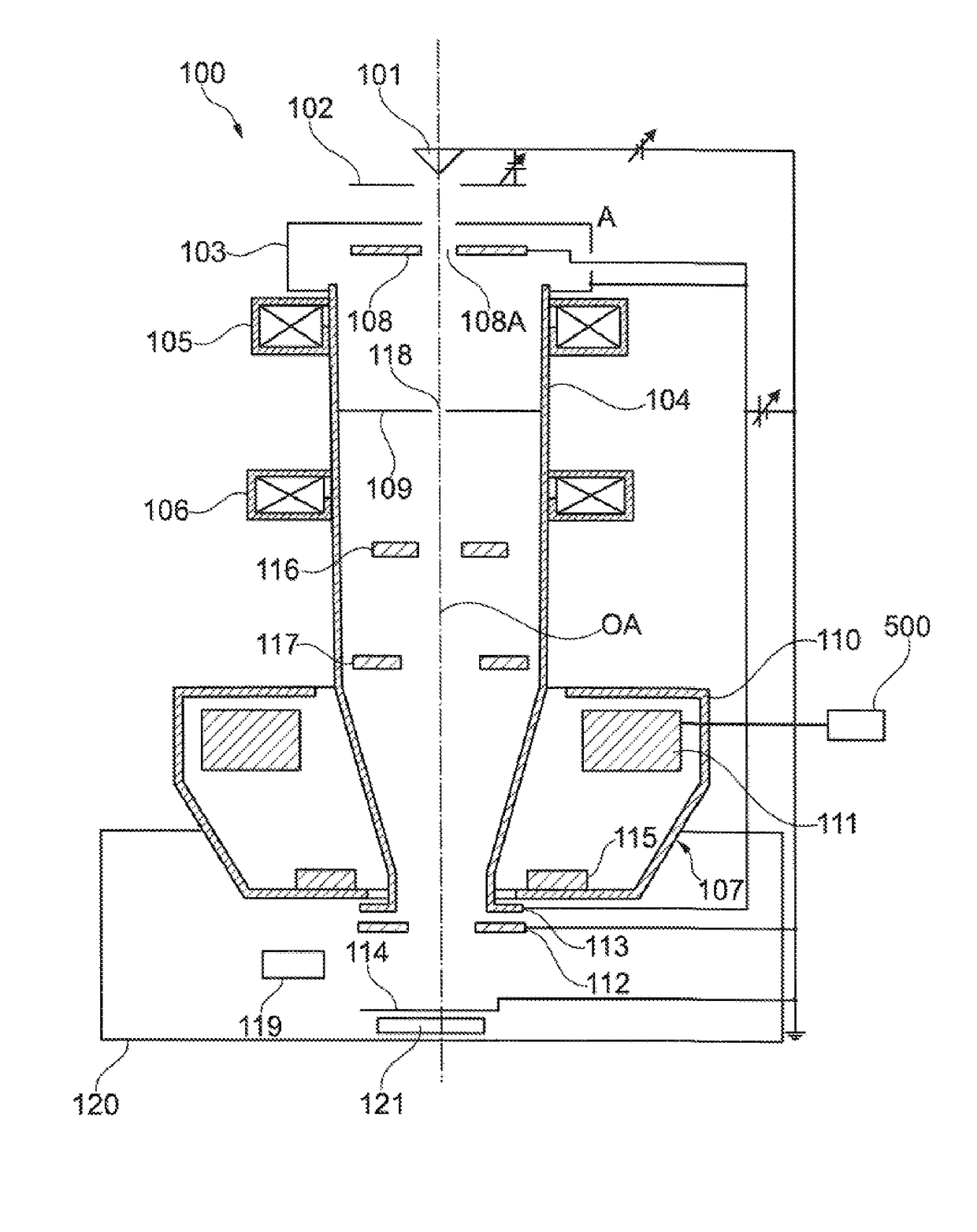
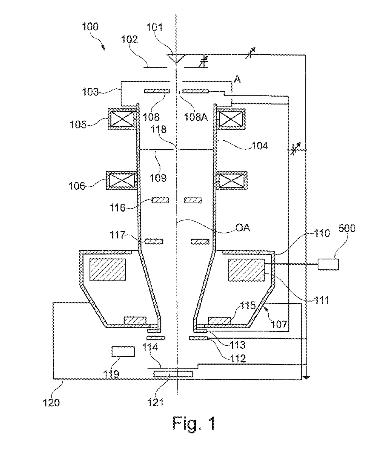
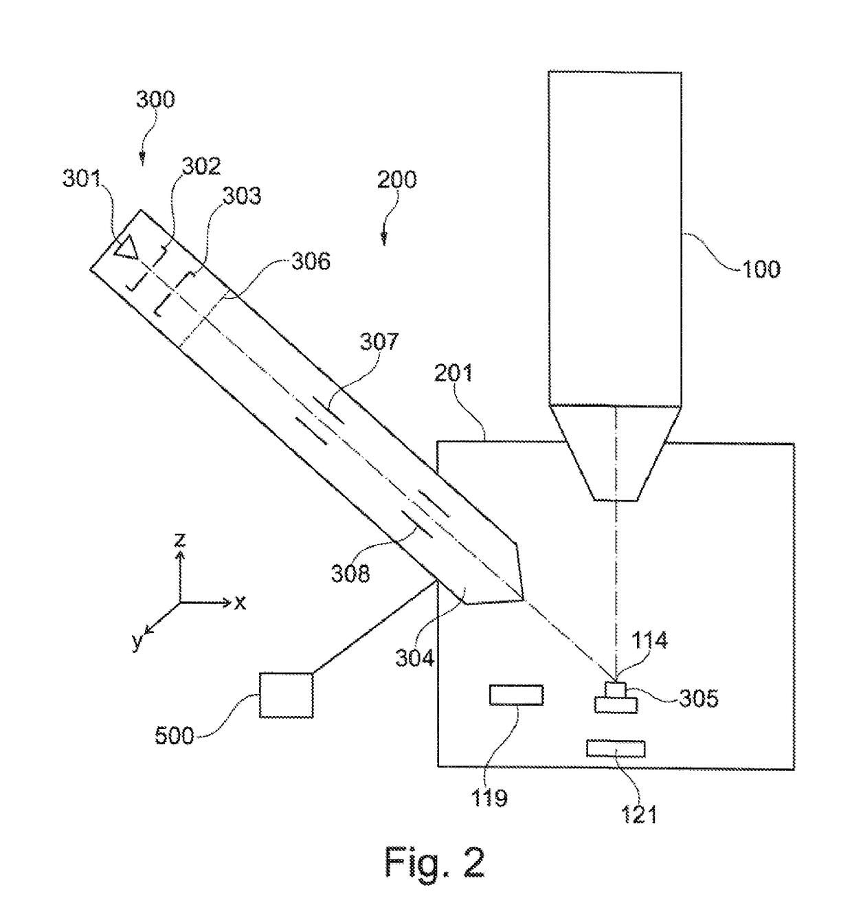
[0072]The system described herein is now explained in more detail by means of particle beam apparatuses in the form of an SEM and in the form of a combination apparatus, which has an electron beam column and an ion beam column. Reference is explicitly made to the fact that the system described herein can be used in any particle beam apparatus, in particular in each electron beam apparatus and / or in each ion beam apparatus. The system described herein relates in particular to particle beam apparatuses comprising one magnetic particle-optical unit or a plurality of magnetic particle-optical units in which the magnetic field of the unit or of the units is generated by the currents of a plurality of coils. By way of example, the particle-optical unit is designed as a beam deflection device, in particular as an objective lens.

[0073]FIG. 1 shows a schematic illustration of an SEM 100. The SEM 100 has a first beam generator in the form of an electron source 101, which is embodied as a cath...


PUM


Abstract

The system described herein relates to a particle beam apparatus for analyzing and/or for processing an object and to a method for operating a particle beam apparatus. The particle beam apparatus is designed for example as an electron beam apparatus and/or an ion beam apparatus. The particle beam apparatus comprises a beam deflection device, for example an objective lens, which is provided with a first coil and a second coil. The first coil is operated with a first coil current. The second coil is operated with a second coil current. The first coil current and/or the second coil current may always be controlled in such a way that the sum of the first coil current and the second coil current (the summation current) or the difference between the first coil current and the second coil current (the difference current) is controlled to a setpoint value.

Description

TECHNICAL FIELD[0001]The system described herein relates to a particle beam apparatus for analyzing and / or for processing an object and to a method for operating a particle beam apparatus and more particularly to a particle beam apparatus designed as an electron beam apparatus and / or an ion beam apparatus.BACKGROUND[0002]Electron beam apparatuses, in particular a scanning electron microscope (also referred to as SEM below) and / or a transmission electron microscope (also referred to as TEM below), are used to examine objects (also referred to as samples) in order to obtain knowledge in respect of the properties and behavior of the objects under certain conditions.[0003]In an SEM, an electron beam (also referred to as primary electron beam below) is generated by means of a beam generator and focused on an object to be examined by way of a beam guiding system. An objective lens is used for focusing purposes, and said objective lens will be discussed in greater detail further below. The...

Claims


Application Information

Patent Timeline
IPC IPC(8): H01J37/147H01J37/30H01J37/24H01J37/28
CPCH01J37/1477H01J37/28H01J37/3007H01J2237/151H01J2237/103H01J2237/152H01J37/24H01J37/141H01J37/21H01J37/147H01J2237/1504H01J37/265
Inventor HEGELE, KLAUSFICHTER, EDGARALIMAN, MICHELPREIKSZAS, DIRKHENDRICH, CHRISTIANMOMMSEN, MOMMESCHNELL, MICHAELSCHUBERT, KAI
Owner CARL ZEISS MICROSCOPY GMBH
Why Eureka
Try Eureka