Energy storage cell, capacitive energy storage module, and capacitive energy storage system

Active Publication Date: 2017-08-17
CAPACITOR SCI
View PDF8 Cites 26 Cited by
  • Summary
  • Abstract
  • Description
  • Claims
  • Application Information

AI Technical Summary

Benefits of technology

[0018]Aspects of the present disclosure address problems with conventional rechargeable electrical energy storage technology by combining a capacitive energy storage device having one or more meta-capacitors (further described below) with a DC-voltage conversion device having one or more switch mode voltage c

Problems solved by technology

The reverse voltage generated will be extremely high if the incremental change in current di occurs over a sufficiently short increment of time dt, and this may damage or destroy the switching element SW1.
A possible issue with this type of circuit is that the turn-on voltage of the diode needs to be reached and be maintained while the switching element SW1 is turned off and the diode is active.
This means that there will always be a voltage drop of, e.g., ˜0.6V across the diode due to current flowing

Method used


Image

  • Energy storage cell, capacitive energy storage module, and capacitive energy storage system
  • Energy storage cell, capacitive energy storage module, and capacitive energy storage system
  • Energy storage cell, capacitive energy storage module, and capacitive energy storage system

Examples


Embodiment Construction

[0059]While various embodiments of the invention have been shown and described herein, it will be obvious to those skilled in the art that such embodiments are provided by way of example only. Numerous variations, changes, and substitutions may occur to those skilled in the art without departing from the invention. It should be understood that various alternatives to the embodiments of the invention described herein may be employed.

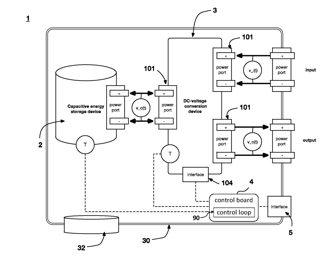
[0060]The present disclosure provides an energy storage cell comprising at least one capacitive energy storage device and a DC-voltage conversion device. FIG. 10 schematically shows a capacitive energy storage cell 1 comprising a capacitive energy storage device 2 that includes one or more meta-capacitors 20 and a DC-voltage conversion device 3, consisting of one or more switch-mode voltage converters 100, e.g. a buck converter, boost converter, buck / boost converter, bi-directional buck / boost (split-pi) converter, Ćuk converter, SEPIC converter, inverting...


PUM


Abstract

The present disclosure provides an energy storage cell comprising at least one capacitive energy storage device and a DC-voltage conversion device. The capacitive energy storage device comprises at least one meta-capacitor. The output voltage of the capacitive energy storage device is the input voltage of the DC-voltage conversion device. The present disclosure also provides a capacitive energy storage module and a capacitive energy storage system.

Description

FIELD OF THE DISCLOSURE[0001]The present disclosure relates generally to a modular energy storage system to simultaneously enable multiple applications and more particularly to an energy storage cell comprising at least one capacitive energy storage device and a DC-voltage conversion device.BACKGROUND[0002]Many technical applications can benefit from rechargeable electrical energy storage. Most rechargeable electrical energy storage systems are based on rechargeable batteries. Rechargeable batteries store and release electrical energy through electrochemical reactions. Rechargeable batteries are used for automobile starters, portable consumer devices, light vehicles (such as motorized wheelchairs, golf carts, electric bicycles, and electric forklifts), tools, and uninterruptible power supplies. Emerging applications in hybrid internal combustion-battery and electric vehicles are driving the technology to reduce cost, weight, and size, and increase lifetime. Grid energy storage appli...

Claims


Application Information

Patent Timeline
IPC IPC(8): H02J7/00
CPCH02J7/0026H02J7/345H02J7/0045H02J7/007H02J1/102H02J7/0018H01G11/56H01G4/18H02J2207/20H02J7/00712H02J7/0025H01G9/00
Inventor KELLY-MORGAN, IANROBINSON, MATTHEW R.FURUTA, PAULMEMBRENO, DANIELLAZAREV, PAVEL IVAN
Owner CAPACITOR SCI
Why Eureka
Try Eureka