Shading Control Network Using a Control Network

a control network and control network technology, applied in the field of integrated home automation systems, can solve the problems of high network management cost, failure to take down the entire network, low cost of implementing technology, etc., and achieve the effect of reducing the number of shades and facilitating the transfer of information

Active Publication Date: 2017-08-24
CRESTRON ELECTRONICS
View PDF12 Cites 17 Cited by
  • Summary
  • Abstract
  • Description
  • Claims
  • Application Information

AI Technical Summary

Benefits of technology

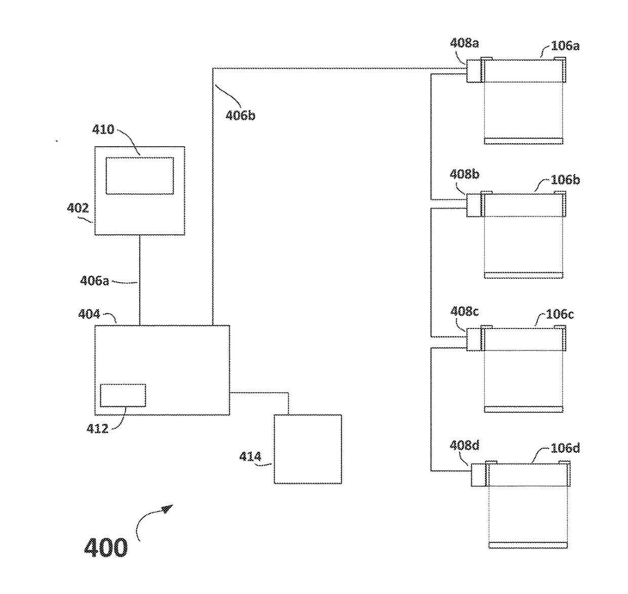
[0049]According to a sixth aspect of the embodiments, a method is provided for programming a shade control network that includes at least one motorized roller shade, the shade control system including a communication network connected to each motorized roller shade, the method comprising connecting a computer having user interface capability to the communication network of the shade control network, transmitting at least a portion of a database of information regarding the shade control network from the computer to the shade control system, transferring power to said shade control network from an intelligent hub via a PoE cable, and storing the portion of the database of information received by the shade control network in a memory in the shade control network.
[0050]According to the sixth aspect of the embodiments, each of the motorized roller shades of the shade control network has memory storage capability, and the method further comprises connecting the computer to a room controller and the shade control network, transmitting substantially all of the database of information regarding the shade control network from the computer to the room controller, transmitting at least a portion of the database of information from the room controller to each of the motorized roller shades, storing the portion of the database of information in memory at each of the motorized roller shades of the shade control network, transmitting an acknowledgement of receipt of the database portion from each of the motorized roller shades to the room controller, and transmitting a report from the room controller to the computer regarding acknowledgement by the at least one motorized roller shade.
[0051]According to the sixth aspect of the embodiments, the programming method further comprises connecting said intelligent hub to the communication network of the shade control system to facilitate transfer of information with the shade control network, and connecting said room controller to said intelligent hub, wherein said room controller is part of an integrated control system, and said room controller is configured to control at least one other control system including a lighting control network in addition to the shade control network. Still further according to the sixth aspect of th

Problems solved by technology

However, the low cost of implementing the technology is offset by the high cost of managing the network.
Additionally, since only one cable is utilized, it can be a single point of failure that takes down the entire network.
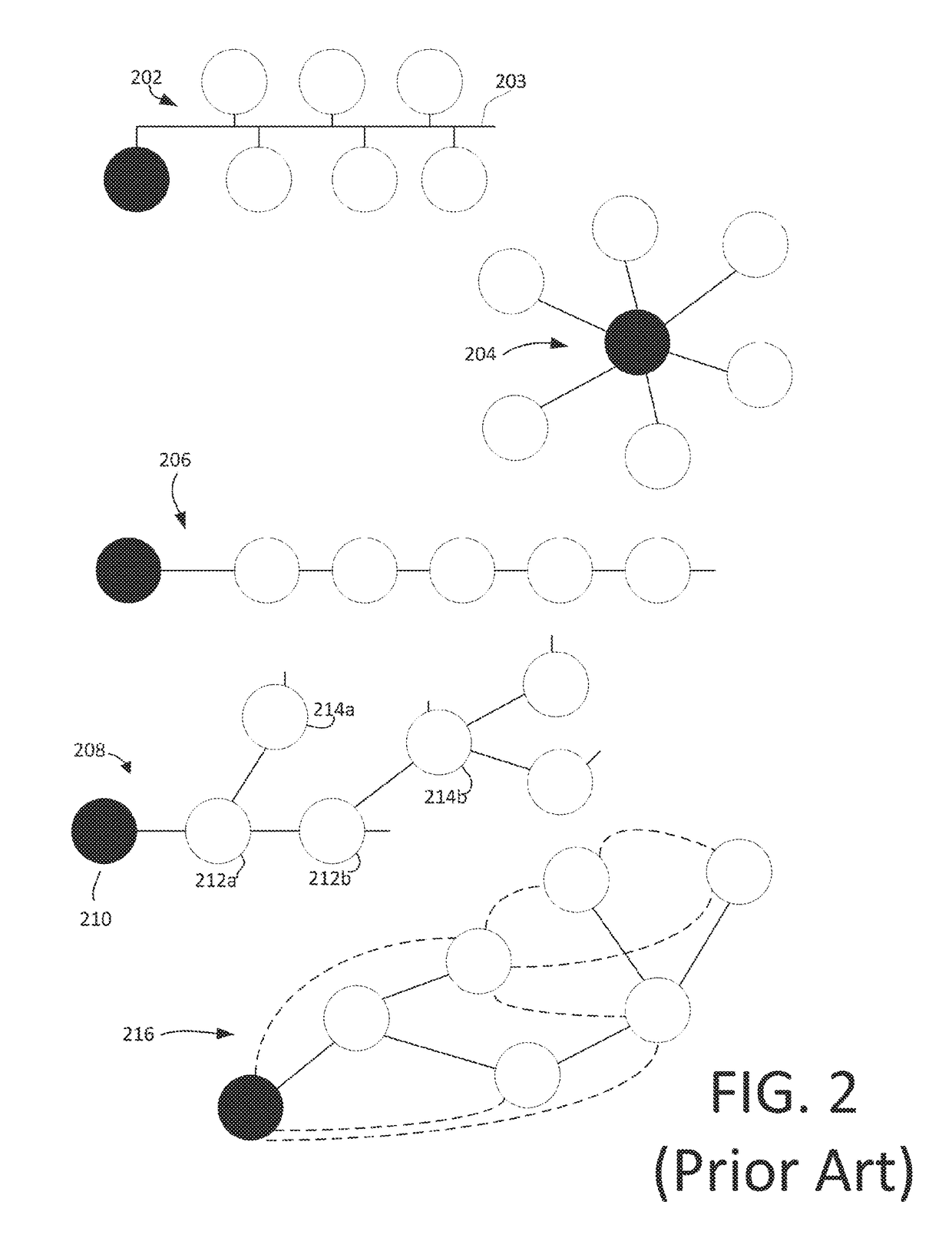
In terms of home (or commercial) automation systems, additional limitations can include that only a limited amount of power can be transferred to devices on bus network 202 from the central node.
If additional nodes are added that require additional power, a new power supply could be required, but there is a limit as to how much power can be transferred over conventional cabling for bus network topology 202.
The primary disadvantage of star network 204 is that the hub represents a single point of failure; if it fails, no communications can take place (whereas in bus network 202, a non-source node (the one or more unshaded nodes) can take over as the source node).
However, each time a new node is added, the cable must be “home-runned” back to the central (or source) node, which can be costly.
In terms of automation systems, daisy chain network 206 is also problematic in terms of power because all of the power needs to be transferred through one cable, similarly to bus network 202; thus, there are practical limitations as to the number of devices that can be attached and/or the total power that can be

Method used


Image

  • Shading Control Network Using a Control Network
  • Shading Control Network Using a Control Network
  • Shading Control Network Using a Control Network

Examples


Embodiment Construction

[0140]The embodiments are described more fully hereinafter with reference to the accompanying drawings, in which embodiments of the inventive concept are shown. In the drawings, the size and relative sizes of layers and regions may be exaggerated for clarity. Like numbers refer to like elements throughout. The embodiments may, however, be embodied in many different forms and should not be construed as limited to the embodiments set forth herein. Rather, these embodiments are provided so that this disclosure will be thorough and complete, and will fully convey the scope of the inventive concept to those skilled in the art. The scope of the embodiments is therefore defined by the appended claims. The detailed description that follows is written from the point of view of a control systems company, so it is to be understood that generally the concepts discussed herein are applicable to various subsystems and not limited to only a particular controlled device or class of devices, such as...


PUM


Abstract

A control system is disclosed that includes a room controller transmitting signals to both a shade control network and a light control network, directing that motorized roller shades and dimmable lights be set to desired intensity levels. The control system further includes an intelligent hub that provides a trickle-charge re-charge current via power-over-Ethernet cables to batteries associated with each of the motorized roller shades for re-charging the batteries, thereby eliminating power supplies being installed within walls. The intelligent hub provides for communication with the room controller based on streaming protocol and with the shade control network based on event-based protocol. A computer running user interface software may be connected to the system to facilitate programming.

Description

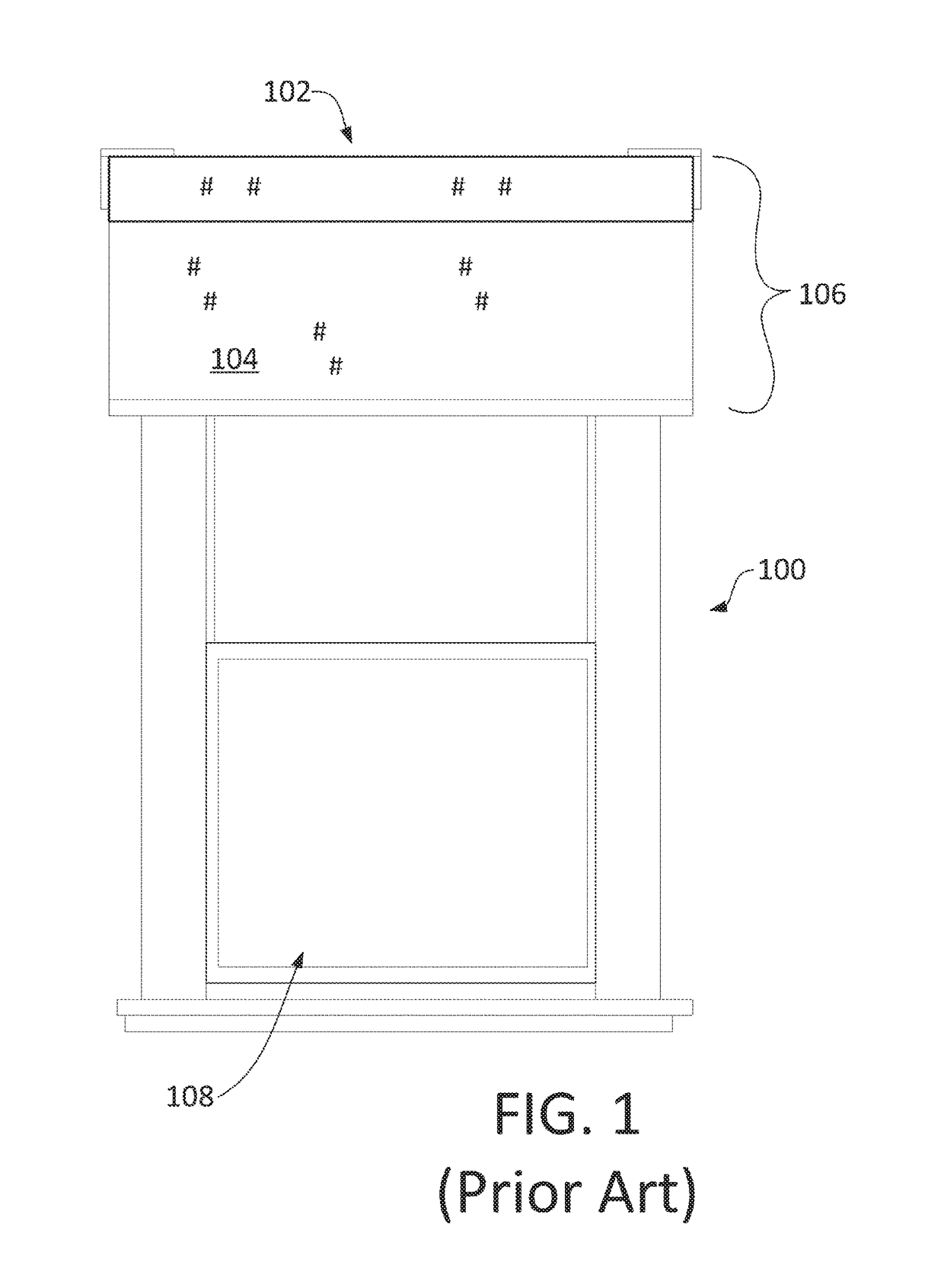
PRIORITY INFORMATION[0001]The present application claims priority under 35 U.S.C. §121 to U.S. Non-Provisional patent application Ser. No. 14 / 306,685, filed 17 Jun. 2014, and further claims priority under 35 U.S.C. §120 to U.S. Non-provisional patent application Ser. No. 14 / 306,656, filed 17 Jun. 2014, the entire contents of both of which are expressly incorporated herein by reference.CROSS REFERENCE TO RELATED APPLICATIONS[0002]Related subject matter is disclosed in co-pending U.S. Non-provisional patent application Ser. No. 14 / 306,656, filed 17 Jun. 2014, entitled “A System and Method for Providing Shading and Lighting Control Using a Control Network.”BACKGROUND OF THE INVENTION[0003]Technical Field[0004]Aspects of the embodiments relate to an integrated home automation system that includes centralized control for controlling motorized shades in a residential home.[0005]Background Art[0006]It is known to control the operation of a motorized shade or drapery by transmitting command...

Claims


Application Information

Patent Timeline
IPC IPC(8): E06B9/68H04L12/931G05B15/02H04L12/28E06B9/72G05B19/06
CPCE06B9/68E06B9/72G05B19/06G05B2219/2653H04L12/2816H04L49/405E06B2009/6809G05B15/02G05B2219/25011G05B2219/2642H04L12/283H04L2012/285
Inventor FELDSTEIN, GEORGE
Owner CRESTRON ELECTRONICS
Why Eureka
Try Eureka