Measuring system for over-the-air power measurements with active transmission

a technology of power measurement and over-the-air transmission, which is applied in the direction of transmitter monitoring, instruments, transmission monitoring, etc., can solve the problems of not showing how to handle a large measuring antenna is placed close to the device under test, and a new set of problems, so as to simplify the construction of the measuring system, simplify the regulation of the signal source, and simplify the effect of the measurement system

Active Publication Date: 2017-08-24
ROHDE & SCHWARZ GMBH & CO KG
View PDF35 Cites 4 Cited by
  • Summary
  • Abstract
  • Description
  • Claims
  • Application Information

AI Technical Summary

Benefits of technology

[0016]According to a further implementation form of the first aspect, the signal source is adapted to be regulated in an analog manner. This alternative also allows for a very simple regulation of the signal source.
[0017]According to a further implementation form of the first aspect, the transmitter module comprises an amplifier or a dampener. This allows for a regulation of the amplitude of the signal transmitted by the transmitter module.
[0018]According to a further implementation form of the first aspect, the transmitter module comprises an input, which is connected to an external signal source. This allows for an especially simple construction of the measuring system, since the signal transmitted by the transmitter module does not need to be generated by the transmitter module.
[0019]According to a further implementation form of the first aspect, the transmitter module comprises a mixer. This allows for regulating the frequency of the signal transmitted by the transmitter in a very simple manner.
[0020]According to a further implementation form of the first aspect, the mixer comprises an input, which is connected to an external signal source. This greatly simplifies the construction of the measuring system.
[0021]According to a further implementation form of the first aspect, the external signal source is a local oscillator, adapted to provide a local oscillator signal to the mixer. The mixer is then adapted to generate an intermediate frequency signal, by mixing with the local oscillator signal. Also this assures a very simple regulation of the frequency of the signal transmitted by the transmitter module.

Problems solved by technology

When measuring such high frequencies, a new set of problems has arisen.
Placing a large measuring antenna close to the device under test is also problematic.
The system shown there especially does not show how to handle devices under test, which can receive signals as well.

Method used


Image

  • Measuring system for over-the-air power measurements with active transmission
  • Measuring system for over-the-air power measurements with active transmission
  • Measuring system for over-the-air power measurements with active transmission

Examples


first embodiment

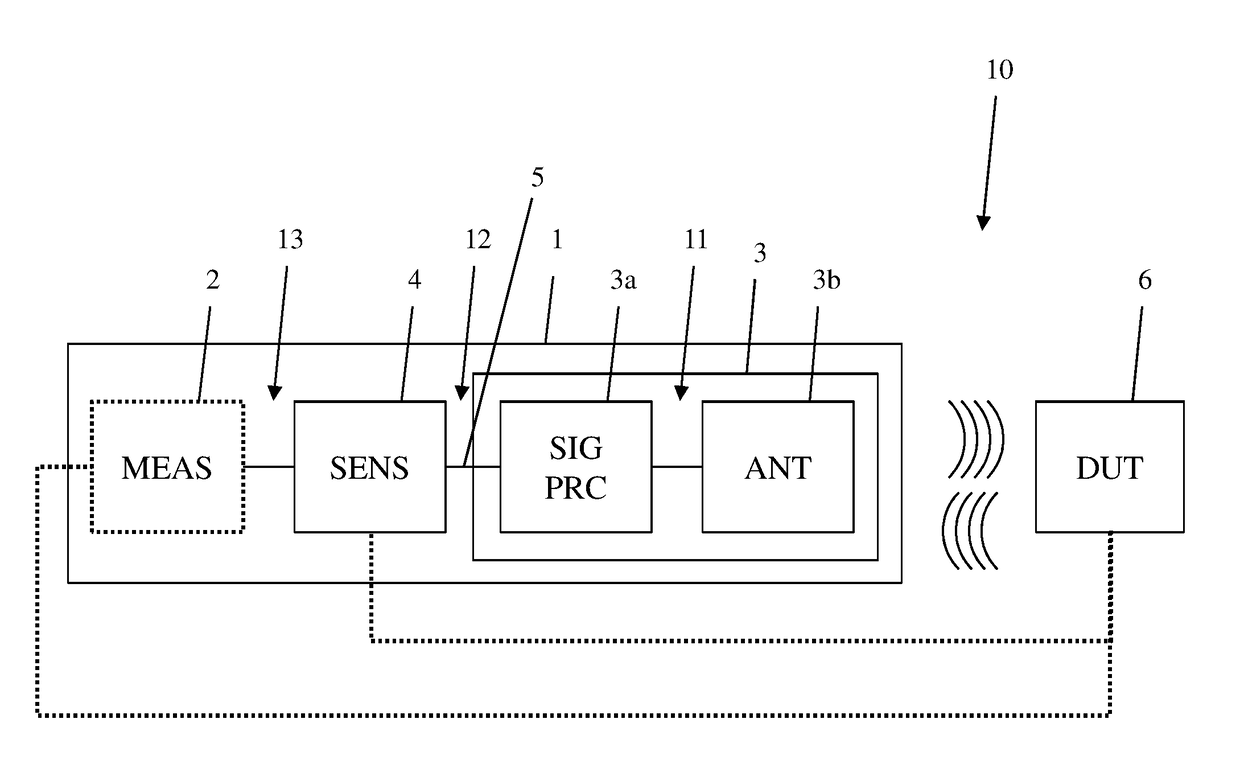
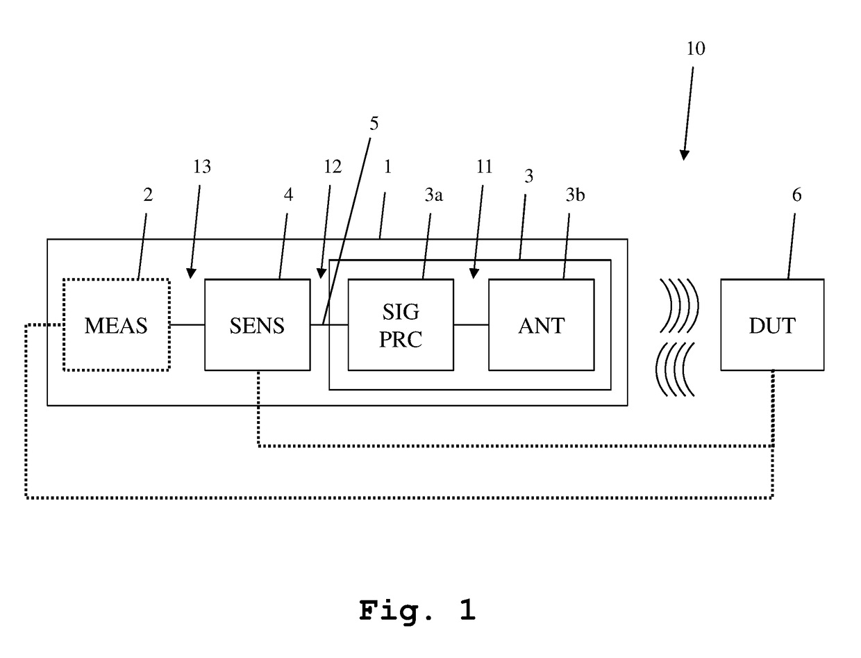
[0038]In FIG. 1, a first embodiment of the measuring system 1 according to the first aspect of the invention is shown. The measuring system 1 comprises a measuring device 2, which is connected to a sensor module 4, which in turn is connected to a signal processing module 3a. The signal processing module 3a comprises a detector module and a transmitter module, which are described in greater detail along FIG. 3 and FIGS. 5-13.

[0039]The signal processing module 3a in turn is connected to an antenna module 3b. The signal processing module 3a and the antenna module 3b form a combined module 3. The signal processing module 3a and the sensor module 4 are connected via a cable 5. The cable 5 can be an electrical cable or an optical cable. Especially, it can be a coaxial cable or a fiber-optic cable.

[0040]The measuring device 2 is a stand-alone measuring device, for example a signal analyzer. It is important to note that the measuring device 2 is only an optional component and not necessary ...

second embodiment

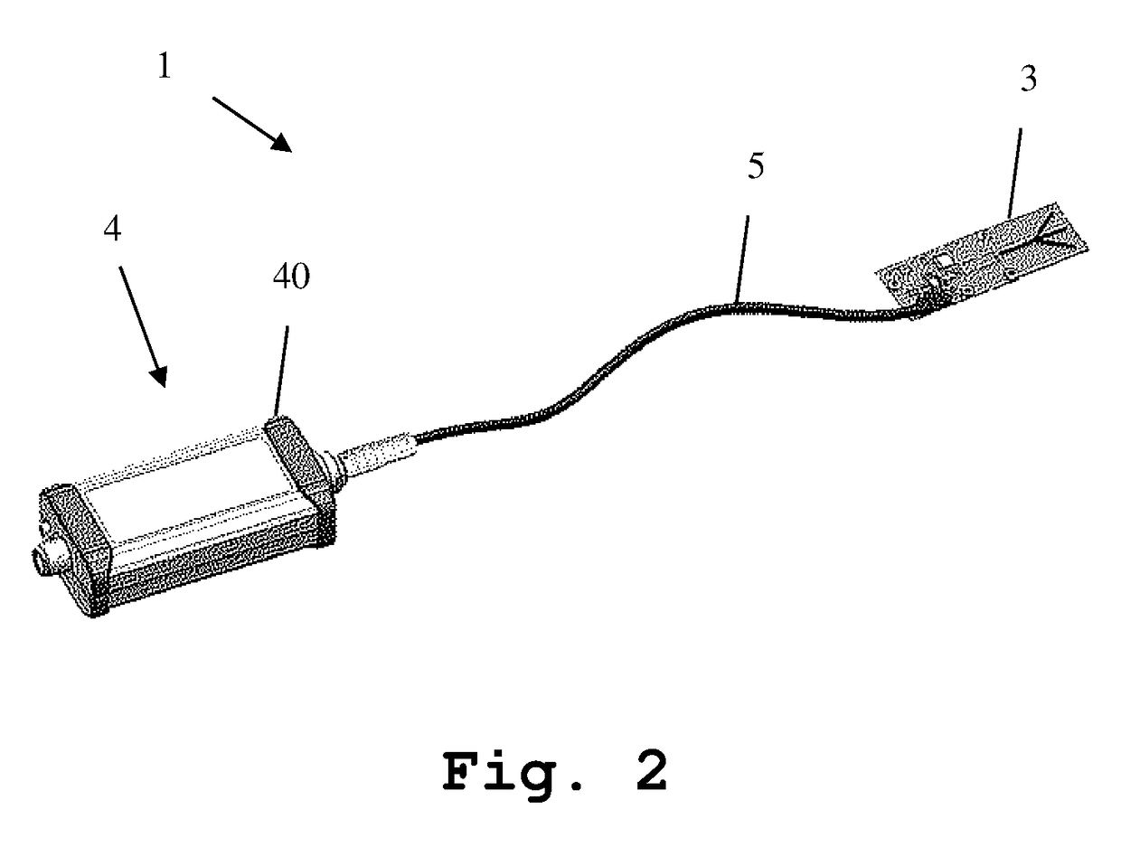
[0048]In FIG. 2, a three-dimensional image of the measuring system 1 is depicted. Especially, the sensor module 4, the cable 5 and the combined module 3, which comprises the signal processing module 3a and the antenna module 3b of FIG. 1, is clearly visible. Here, it is especially evident that the sensor module 4 comprises a housing 40, which does not encompass the signal processing module 3a and the antenna module 3b, which are comprised by the combined module 3. Also, it is shown here, that the combined module 3 comprises a single printed circuit board, which holds all further components of the combined module 3.

[0049]Regarding the specific construction and function of the sensor module 4, the signal processing module 3a and the antenna module 3b, it is referred to FIG. 3 to FIG. 13.

third embodiment

[0050]In FIG. 3, the signal processing module 3a and the antenna module 3b of FIG. 1 are shown in greater detail. Here, the detector module 3a and the antenna module 3b are integrated into a combined module 3. The combined module 3, comprises an antenna 34, which is connected to a transformer 33. Both, the antenna 34 and the transformer 33 are arranged on the antenna module 3b part of the combined module 3. The antenna 34 advantageously is a planar antenna, advantageously a planar slotline antenna. In order to achieve optimal reception and transmission conditions without interfering reflections, an area surrounding the antenna 34 can be coated in radio frequency absorbing material. Also it is possible to slant all surfaces of the system 1 away from a normal of a main radiation direction of the antenna 34, so as to minimize reflections. Also a minimizing of surfaces facing the main radiation direction of the antenna 34 is beneficial for the same reason.

[0051]The transformer 33 is con...


PUM


Abstract

A measuring system for performing over the air power measurements is provided. The measuring system comprises, within a single housing, a detector module, comprising a detector input, a transmitter module, comprising a transmitter output, and an antenna. The detector input and the transmitter output are at least temporarily connected. At least the transmitter output or the detector input are at least temporarily connected to the antenna.

Description

RELATED APPLICATIONS[0001]The present application is a continuation-in-part of U.S. application Ser. No. 15 / 214,114, filed on Jul. 19, 2016, which claims priority to European Patent Application EP 16 156 454.7, filed on Feb. 19, 2016, the entire contents of which are incorporated herein by reference.TECHNICAL FIELD[0002]The invention relates to a measuring system for wirelessly measuring high frequency signals, especially the power of high frequency signals, and measuring a reaction of a device under test to signals.BACKGROUND ART[0003]In recent years, the frequencies employed for transmitting communications signals have continually risen. When measuring such high frequencies, a new set of problems has arisen. Directly connecting a device under test to a measuring device influences the measuring results. Placing a large measuring antenna close to the device under test is also problematic.[0004]For example, the German patent application DE 199 13 338 A1 shows a measuring circuit for ...

Claims


Application Information

Patent Timeline
Patent Type & Authority Applications(United States)
IPC IPC(8): H04B17/10H04B17/00H04B17/318
CPCH04B17/102H04B17/0085H04B17/318G01R21/01G01R19/04G01R21/10G01R21/14G01R23/00G01R29/0878
Inventor GALLHAUSER, MARKUSPERNDL, WERNERVOSS, NINO
Owner ROHDE & SCHWARZ GMBH & CO KG
Why Eureka
Try Eureka