

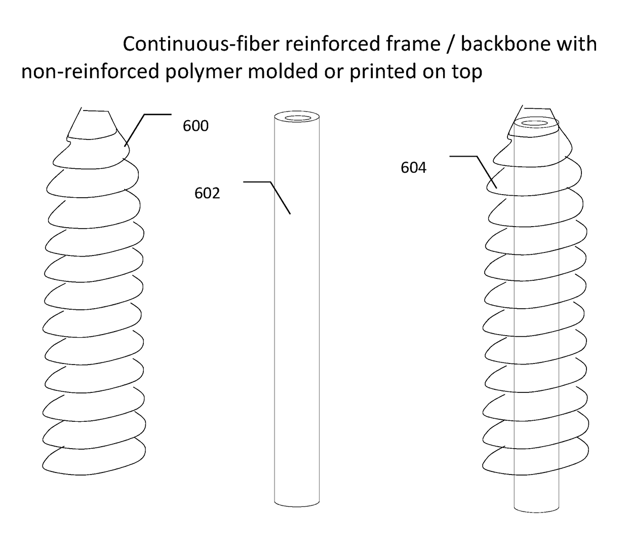
Continuous-fiber reinforced biocomposite medical implants
a biocomposite, fiber-reinforced technology, applied in the direction of prosthesis, internal osteosynthesis, osteosynthesis devices, etc., can solve the problem of difficult problem of biocomposite fiber-reinforced materials with the requisite provided with an adequate solution, and achieve the effect of improving mechanical properties, high strength and stiffness of implants
- Summary
- Abstract
- Description
- Claims
- Application Information
AI Technical Summary
Benefits of technology
Problems solved by technology
Method used
Image

Examples
example # 1
EXAMPLE #1
Large Diameter Pins
[0229]Below example describes production of large diameter orthopedic pins with reinforced biocomposite materials. This example demonstrates how different medical implant pins comprised of reinforced biocomposite materials can have different performance properties with regard to flexural modulus and strength, both at time zero (following production) and following simulated degradation, relating to the compositional structure, geometry, and composition of each type of pin.
[0230]Materials & Methods
[0231]Three types of pin implants, each of outer diameter 6 mm and 5 cm length were produced using reinforced composite material. Material composite was comprised of PLDLA 70 / 30 polymer reinforced with 50% w / w, 70%, or 85% w / w continuous mineral fibers. Mineral fibers composition was approximately Na2O 14%, MgO 5.4%, CaO 9%, B2O3 2.3%, P2O5 1.5%, and SiO2 67.8% w / w. Testing samples were manufactured by compression molding of multiple layers of composite material ...
example # 2
EXAMPLE #2
Small Diameter Pins
[0247]Below example describes production of small diameter orthopedic pins with reinforced biocomposite materials. This example demonstrates how different medical implant pins comprised of reinforced biocomposite materials can have different performance properties with regard to flexural modulus and strength, both at time zero (following production) and following simulated degradation (for example upon insertion to the body), relating to the compositional structure, geometry, and composition of each type of pin.
[0248]Materials & Methods
[0249]Three types of pin implants, each of outer diameter 2 mm and 5 cm length were produced using reinforced composite material. Material composite was comprised of PLDLA 70 / 30 polymer reinforced with 50% w / w or 70% w / w continuous mineral fibers. Mineral fiber composition was approximately Na2O 14%, MgO 5.4%, CaO 9%, B2O3 2.3%, P2O5 1.5%, and SiO2 67.8% w / w. Testing samples were manufactured by compression molding of mult...
example # 3
EXAMPLE #3
Plates
[0264]Below example describes production of thin orthopedic plates with reinforced biocomposite materials. This example demonstrates how different medical implant plates comprised of reinforced biocomposite materials can have different performance properties with regard to flexural modulus and strength, both at time zero (following production) and following simulated degradation, relating to the compositional structure, geometry, and composition of each type of plate.
[0265]Materials & Methods
[0266]Four types of plate implants, each with a thickness of 2 mm, width of 12.8 mm and 6 cm length were produced using reinforced composite material. Material composite was comprised of PLDLA 70 / 30 polymer reinforced with 50% w / w or 70% w / w continuous mineral fibers. Mineral fibers composition was approximately Na2O 14%, MgO 5.4%, CaO 9%, B2O3 2.3%, P2O5 1.5%, and SiO2 67.8% w / w. Testing samples were manufactured by compression molding of multiple layers of composite material in...
PUM
| Property | Measurement | Unit |
|---|---|---|
| Length | aaaaa | aaaaa |
| Length | aaaaa | aaaaa |
| Fraction | aaaaa | aaaaa |
Abstract
Description
Claims
Application Information