
Multi-mode control for solid state lighting

a technology of lightemitting diodes and solid-state lighting, which is applied in the direction of electric lighting sources, electroluminescent light sources, and use of semi-conductor lamps, can solve the problems of premature occlusion of lamps, perceptible flicker, and slow adoption of ssl lamps as suitable replacements compared to other lighting methods, and achieves the effect of increasing power factor correction and improving total harmonic distortion performan

Active Publication Date: 2017-08-31
DIALOG SEMICONDUCTOR INC
View PDF6 Cites 46 Cited by
  • Summary
  • Abstract
  • Description
  • Claims
  • Application Information

AI Technical Summary

Benefits of technology

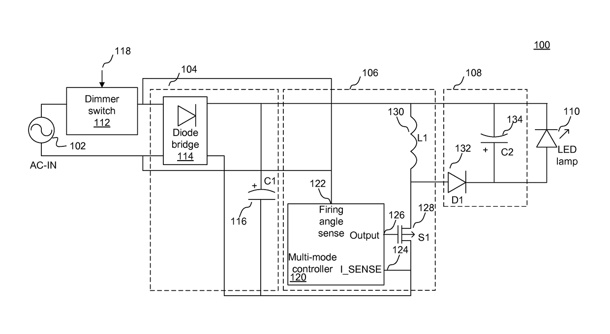
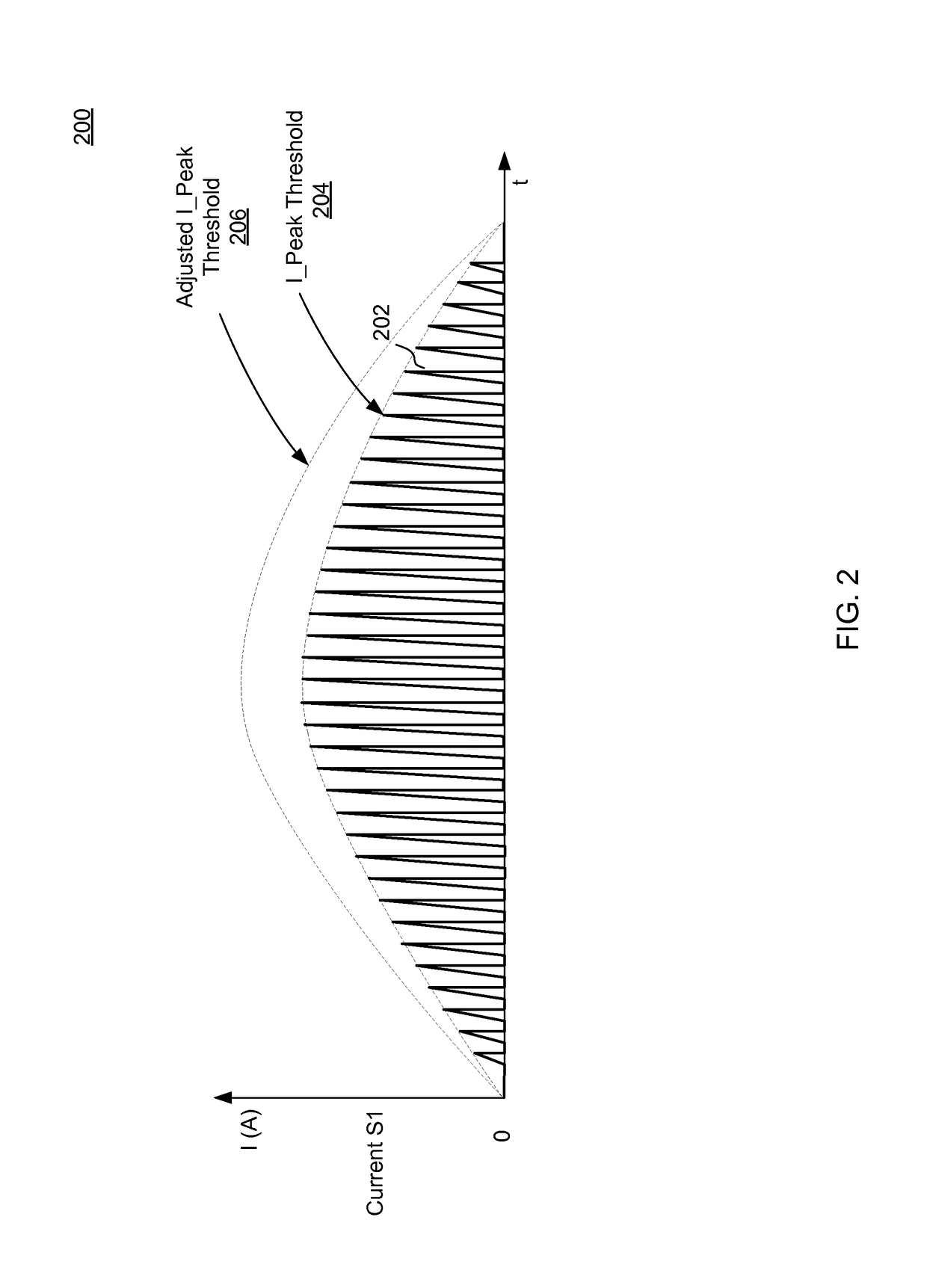
The disclosed multi-mode controller features a control scheme that combines current shaping, switching cycle modulation, and hybrid regulation modes. It also uses hysteresis to switch between modes. This control scheme ensures that the dimmer switch operates properly and avoids flickering. Additionally, it improves overall performance by reducing harmonic distortion and increasing power factor correction. The multi-modal control scheme is also consistent across different types of dimmer switches.

Problems solved by technology

In some applications, however, the adoption of SSL lamps as being suitable replacements compared to other lighting methods has been slow.
For example, in applications where the brightness of the light source is adjusted, such as in a dimmable lighting system, methods employed to drive an incandescent lamp, if applied to an LED lamp, may cause the LED lamp to prematurely turn off when the LED lamp is in an ON phase, resulting in a perceivable flicker.
These techniques, however, often cause the dimmer switch to provide maximum of light output from the LED under all operating conditions.
Moreover, LED output regulation control schemes suited for dimmable lighting system may not be suitable for LED lighting systems that do not use dimmer switches.

Method used


Image

  • Multi-mode control for solid state lighting
  • Multi-mode control for solid state lighting
  • Multi-mode control for solid state lighting

Examples


Embodiment Construction

[0017]The Figures (FIG.) and the following description relate to embodiments of the present disclosure by way of illustration only. It should be noted that from the following discussion, alternative embodiments of the structures and methods disclosed herein will be readily recognized as viable alternatives that may be employed without departing from the principles of the present disclosure.

[0018]Reference will now be made in detail to several embodiments of the present disclosure, examples of which are illustrated in the accompanying figures. It is noted that wherever practicable similar or like reference numbers may be used in the figures and may indicate similar or like functionality. The figures depict embodiments of the present disclosure for purposes of illustration only. One skilled in the art will readily recognize from the following description that alternative embodiments of the structures and methods illustrated herein may be employed without departing from the principles ...


PUM


Abstract

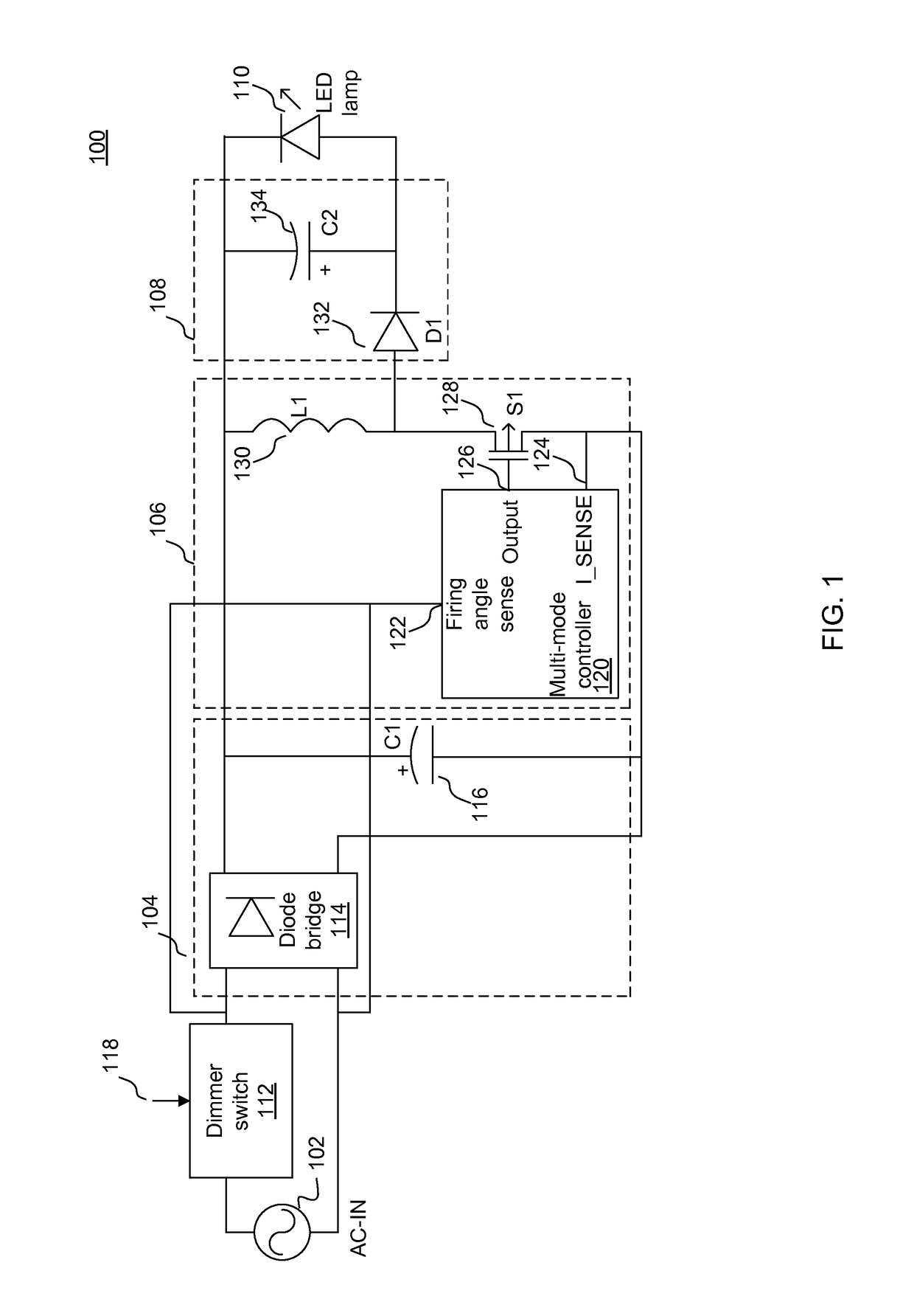
A multi-mode control scheme for an LED lamp system uses the detected firing angle of an AC input voltage waveform to select from multiple regulation modes. In operation, a current controller compares the detected firing angle to one or more specified thresholds and selects the appropriate regulation scheme based on the comparison result. When the detected firing angle is less than a first firing angle threshold, the controller employs a current shaping regulation mode. When the detected firing angle is greater than a second firing angle threshold, the controller employs a switching cycle-I_Peak modulation regulation mode. And when the detected firing angle is greater than the first firing angle threshold and less than the second firing angle threshold, the controller employs a hybrid regulation mode.

Description

CROSS REFERENCE TO RELATED APPLICATIONS[0001]This application claims priority under 35 U.S.C. §119(e) from co-pending United States Provisional Patent Application No. 62 / 050,689, filed on Sep. 15, 2014, which is incorporated by reference herein in its entirety.BACKGROUND[0002]1. Technical Field[0003]The present disclosure relates to driving Light-Emitting Diode (LED) lamps and, more specifically, to regulating the energy supplied to the LED lamp under multiple operating conditions.[0004]2. Description of the Related Arts[0005]A wide variety of electronics applications now use solid state lighting (SSL) devices, such as LED lamps, as replacements for incandescent lamps. These applications include architectural lighting, automotive lighting, backlights for liquid crystal display devices, flashlights, and electronic signs. SSL devices have several advantages compared to incandescent lamps, including higher efficiency, improved directionality, improved reliability, longer life time, and...

Claims


Application Information

Patent Timeline
Patent Type & Authority Applications(United States)
IPC IPC(8): H05B33/08H05B44/00
CPCH05B33/0845H05B33/0815H05B45/31H05B45/10H05B45/3725H05B45/355H05B45/59H05B45/48Y02B20/30
Inventor WANG, XIAOYANFENG, GUANGSHI, NAN
Owner DIALOG SEMICONDUCTOR INC
Learn More