3D printer and method for printing an object using a curable liquid

a curable liquid and 3d printing technology, applied in the field of additive manufacturing, can solve the problems of difficult or impossible use of materials as the print feedstock for 3d printing using current 3d printing technology, difficult 3d printing using low viscosity materials or using high viscosity materials, and general restriction of 3d printing of parts using low viscosity liquids, etc., to achieve the effect of high toughness and under the melting point of the binder

Inactive Publication Date: 2017-09-07
TELAMENS INC
View PDF6 Cites 71 Cited by
  • Summary
  • Abstract
  • Description
  • Claims
  • Application Information

AI Technical Summary

Benefits of technology

[0022]In accordance with the invention there is also provide a 3D printed part comprising a thermoplastic or food shell surrounding a core, wherein the core is selected from the group consisting of a thermoset polymer, a composite comprising a thermoset polymer and a food material. Optionally, the thermoset polymer is made from the monomers selected from the group consisting of dicyclopentadiene, norbornadiene, substituted dicyclopentadiene, substituted norbornadiene, cyclooctene, cyclic olefins, and mixtures thereof. Optionally, the thermoset polymer is a polysiloxane. Optionally the thermoset is an epoxy resin. In some implementations the part includes an organometallic. Optionally the part includes a void volume between about 1% and about 99% (e.g., between about 5% and 95%). Optionally, the thermoplastic comprises more than one type of thermoplastic.
[0023]In another aspect, the invention provides for a 3D printer for producing a part using a paste. The printer includes a chamber capable of containing the paste wherein the chamber includes at least one movable wall. There is also included a mechanism for moving the wall which is CNC controlled. The chamber furthermore includes an opening through which the paste can be extruded. The printer includes a stage, such as a flat surface or plate (e.g., a 3D printer surface). Optionally the stage or a portion of the stage is removable (e.g., designed with quick release fasteners to allow part or the whole stage to be removed). The stage is disposed for receiving the extruded material from the opening in the chamber and the relative position of the stage and opening is CNC controlled. In some implementations, the mechanism for moving the wall is a linear actuator in mechanical communication with the wall. Optionally the movable wall is configured as an extruder screw drive or continuous cavity pump. Optionally, the printer comprises more than one of the chambers (e.g., two or more). Optionally, the 3D printer further includes a nozzle through which the paste can be extruded, the nozzle being attached to the chamber opening. Optionally, the 3D printer further includes a nozzle through which the paste can be extruded and a static mixer in fluid communication with at least two chambers and the nozzle. Optionally the nozzle is disposable. Optionally or additionally the static mixer is disposable. Additionally or alternatively, the 3D printer further includes an energy source directing energy at the extruded material (e.g., an energy source fixed to the chamber). For example, the extruded material can be disposed between the energy source and the stage. One example includes an energy source that provides heat. The energy source can be selected from the group consisting of a hot air gun, an infra-red (IR) lamp, a resistive heater, and combinations of these. In some implementations, the 3D printer further includes a thermal insulation disposed to surround the extruded material deposited on the stage. For example, in some implementations, the energy source is capable of heating the extruded material to a temperature of at least about 35 degrees Celsius (e.g., at least about 40 degree Celsius, at least 50 degree Celsius, at least 60 degree Celsius, at least 70 degree Celsius, at least 80 degree Celsius, at least 90 degree Celsius, at least 100 degree Celsius, at least degree Celsius, at least 120 degree Celsius). In some implementations the thermal insulation is capable of maintaining the temperature of extruded material on the stage at a temperature of at least about 35 degrees Celsius (e.g., at least about 40 degree Celsius, at least about 50 degree Celsius, at least about 60 degree Celsius, at least about 70 degree Celsius, at least about 80 degree Celsius, at least about 90 degree Celsius, at least about 100 degree Celsius, at least about 120 degree Celsius). In some implementations, the 3D printer further includes an extruder for deposition of a second material on the stage. For example, the second extruder can be a clay extruder, a fused deposition modeling type extruder, a paste extruder, a liquid extruder or an applicator. The second extruder can include an energy source directing energy at the extruded second material. In some further implementations, the chamber opening of the 3D printer includes a nozzle through which the paste can be extruded and the nozzle is stationary relative to the chamber when the 3D printer is producing the part. In some implementation, the chamber, wall, linear actuator, and opening are capable of extruding a feed material having a viscosity greater than 1 million centipoise through said opening (e.g., greater than 2 million centipoise, greater than 10 million centipoise). Optionally, the chamber walls are metal (e.g., stainless steel or Hastelloy). Also optionally, the chamber is rated to withstand an internal pressure of at least 2000 psig. In some implementations, the chamber is in the form of a syringe. In other implementations the chamber is in the form of a screw extruder or continuous cavity pump. In some other implementations, the 3D printer, further includes a tube and a nozzle, wherein the tube is disposed between the chamber and nozzle and wherein the chamber, nozzle and tube are in fluid communication with each other and wherein the paste extrudes from the chamber, through the tube and through the nozzle to be deposited on the stage. Optionally, the tube is a flexible high pressure tube. Also optionally, the tube comprises metal. Optionally, the tube and chamber are connected e.g., in fluid communication with an in-line mixer. Optionally, the in-line mixer is disposable. Optionally the nozzle is disposable. In some implementations, the chamber includes a cooling loop (e.g., a cooling jacket such as supplied by a cooled glycol solution). In some implementations, the tube includes a cooling loop. In some implementations, the chamber opening includes a stopcock for controlling (e.g., stopping flow out of the chamber) or a one way valve (e.g., for allowing flow only out of the chamber). For example, the contents of the interior of the chamber can be isolated from material (e.g., air) outside of the chamber. In some implementations, the 3D printer includes a pressure release valve or pressure break seal disposed on the chamber. In some implementations, the 3D printer includes a pressure release valve or pressure break seal disposed on the static mixer.
[0024]In a further aspect, the invention provides a method of producing a 3D part using a paste (e.g., as the feed material, a first deposited material). The method includes extruding an uncured feed material through a nozzle and onto a stage in a layer-by-layer fashion. The method also includes at least partially curing the deposited uncured material while extruding the uncured feed material. The method produces a deposited part that is an at least partially cured material. Optionally the uncured feed material has a viscosity of at least greater than about 1 million centipoise (e.g., greater than 2 million centipoise, greater than 10 million centipoise) while being extruded through the nozzle. Optionally, the uncured feed material is fed through the nozzle using a syringe equipped with a linear actuator. In some implementations, the uncured feed material is fed through the nozzle using a screw extruder or a progressive cavity pump. In some implementations the method includes depositing a support material (e.g., a second material) on the stage in a layer by layer fashion. Optionally the support material is an uncured ceramic material. Optionally the support material is at least partially cured after being extruded. Also optionally, the cured or partially cured support material is more brittle than the other, non-support material. In an alternative description, the first cured or partially cured deposited material has a higher toughness than the second cured or partially cured support material. For example the first cured or partially cured material can have a toughness that is greater than about 0.1 KJ/m2 (e.g., greater than about 1 KJ/m2) and the second cured or partially cured material can have a toughness that is less than about 0.1 KJ/m2 (e.g., less than about 0.01 KJ/m2). Optionally, the first cured or partially cured deposited material is more resilient than the second cured or partially cured support mat

Problems solved by technology

Although many materials can be used to make 3D printed parts, many materials are difficult or impossible to use as the print feedstock using current 3D printing technology.
3D printing using low viscosity materials or using high viscosity materials can be difficult.
3D Printing of parts using low viscosity liquids is generally restricted to stereolithographic methods.
This limitation is due to the fact that liquids flow and do not maintain structural integrit

Method used


Image

  • 3D printer and method for printing an object using a curable liquid
  • 3D printer and method for printing an object using a curable liquid
  • 3D printer and method for printing an object using a curable liquid

Examples


embodiments

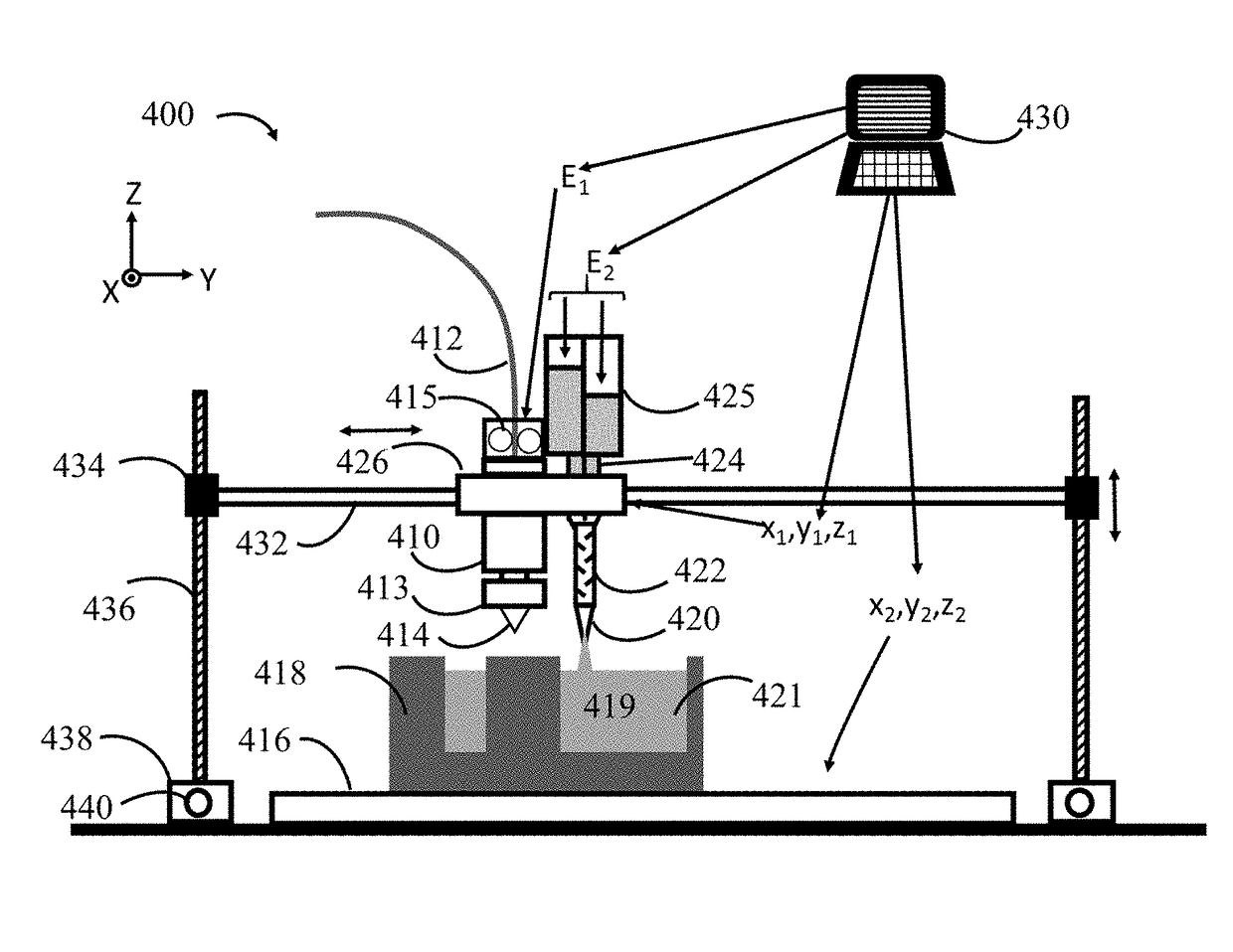
[0064]Using the equipment, methods and systems described herein, a curable liquid can be used for making parts. The liquid material can be cured or partially cured during 3D printing of the part. For example, 3D printers and methods are described that can be used for printing using liquids of low, medium and high viscosities. For example, 3D printers are described that can be used for printing using two part epoxies, food pastes, high viscosity silicones and pastes including metal particles.

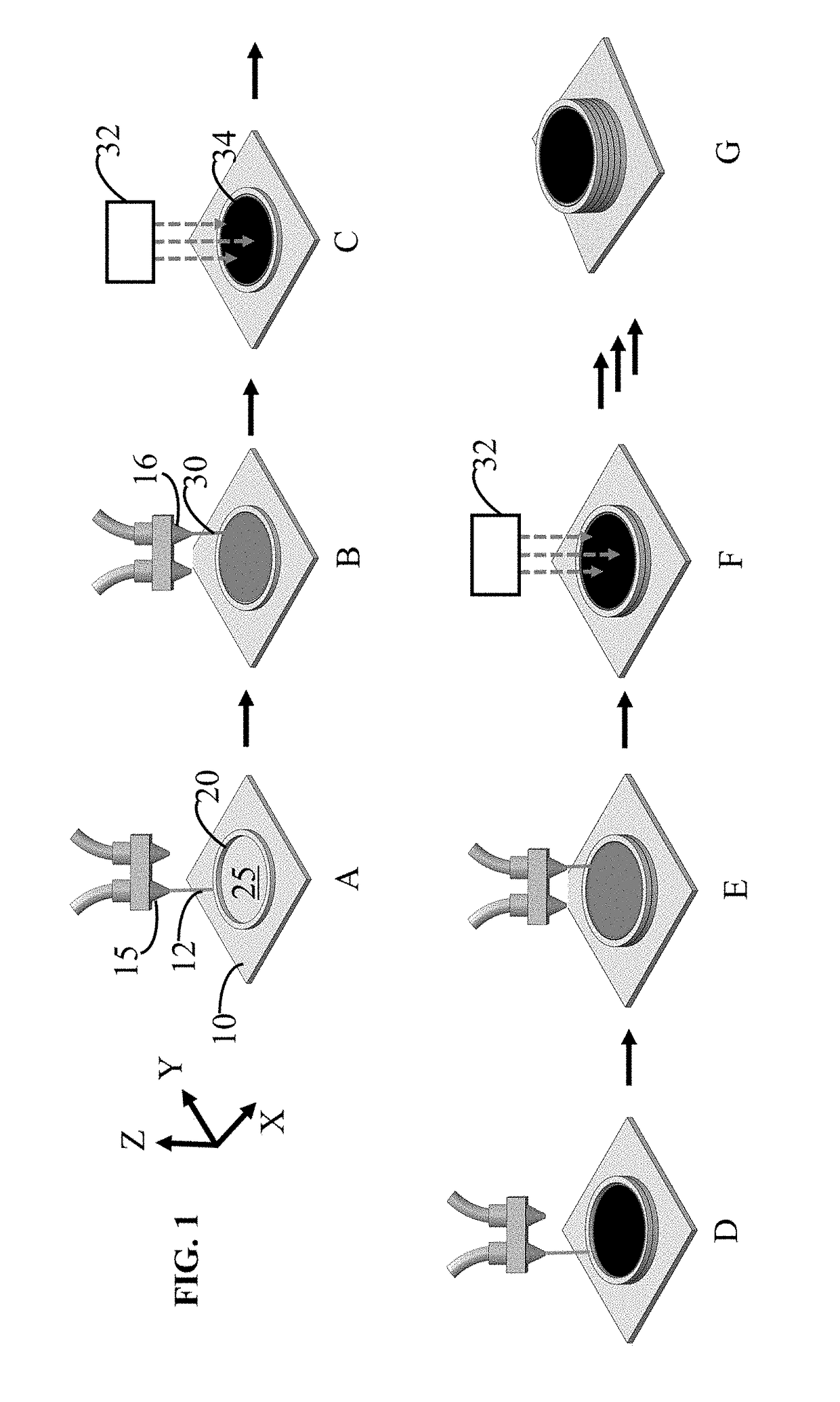
[0065]FIG. 1 is a pictorial flow diagram showing an embodiment of a method for printing a part. The method includes: step A, print a container; step B, infill the container; step C, cure the infill; step D, increase the container size; step E, add additional infill; step F, cure the additional infill; and step G, repeat steps D-F until desired part is made. Details for these steps are outlined below.

[0066]Step A is to print a container. The container is a portion of the final part to be printed. ...

example 1

[0145]Computer Aided Design was used to design the model shown in FIG. 14A as an isometric projection and 14B as a front cross cut view. The model is for a part having a diameter of 5 cm and a height of 2 cm. The model also featured a hole in the center with a diameter of 2 cm and depth of 1.5 cm. Slicing program Simplfy3D was then used to produce G-code that could be used to print a part based on the model using a Flashforge 3D printer (Flashforge, USA) and red ABS filament

[0146]The conditions for printing were:

[0147]Extruder: Nozzle diameter 0.4 mm; Retraction distance 1.00 mm; Retraction speed 1200 mm / min;

[0148]Layers: Primary layer height 0.2 mm; Top solid layers 3; Bottom solid layers 3; Outline / perimeter shells 2; Outline Direction inside out; First layer height 90%; First layer width 100%; First layer speed 50%; Start point optimize start points for fastest printing speed

[0149]Additions: Use skirt / Brim; Skirt layers 1; Start offset from part 4 mm; Skirt outlines 2; Use raft l...

example 2

[0154]FIG. 16 shows a part that can be made by the methods described herein. The part consists of negative stiffness honey comb 1610 that has one row 1620 filled with polydicylcopentadiene (p-DCPD). The honeycomb is made by 3D printing of ABS under conditions similar to those in example 1. The p-DCPD is made by mixing dicyclopentadiene (DCPD) at >40 degree Celsius and ROMP catalyst ((1,3-Bis(2,4,6-trimethylphenyl)-2-imidazolidinylidene)dichloro(phenylmethylene)(tricyclohexylphosphine)ruthenium, Aldrich Cat no 569747), in a ratio of 6.8 mg catalyst to 50 mL DCPD. Iterations of printing honeycomb and filling with DCPD+catalyst can produce the part.


PUM

PropertyMeasurementUnit
Volumeaaaaaaaaaa
Shapeaaaaaaaaaa
Energyaaaaaaaaaa

Abstract

Additive manufacturing methods and apparatus are described for the productions of parts using feedstocks that are cured. The parts are produced in a layer-by-layer fashion by forming in situ a container, filling the container with a liquid and curing the liquid.

Description

RELATED APPLICATIONS / CLAIM OF PRIORITY[0001]This application claims priority from U.S. provisional application Ser. No. 62 / 304,366 filed Mar. 7, 2016 and 62 / 304,371 filed Mar. 7, 2016. The forgoing applications are incorporated by reference herein.FIELD OF THE DISCLOSURE[0002]The present disclosure relates generally to additive manufacturing. More particularly this disclosure relates to 3D printing a 3D printed container and filling the container.BACKGROUND OF THE INVENTION[0003]3-D printing is an additive manufacturing process that builds a part in a layer-by-layer fashion to create a three-dimensional object from a digital model. Initially developed in the mid 1980's and used subsequently in highly specialized industries with the expertise and financial means to mitigate the high costs, 3-D printing has recently become a technology that is cheap and accessible to almost anyone. Today's 3D printers include room sized systems but are more typically desktop instruments and can be use...

Claims


Application Information

Patent Timeline
IPC IPC(8): A23P20/25B33Y70/00A23L3/00B29C67/00B33Y50/02A23P30/20B33Y10/00B33Y80/00
CPCB33Y50/02B29C67/0088A23L3/00B29K2063/00B29K2055/02B29K2003/00A23P2020/253A23V2002/00A23P20/25B33Y10/00B33Y70/00B33Y80/00B29C67/0092B29C67/0055A23P30/20B29C64/106B29C64/336
Inventor WARNER, BENJAMIN P.DE REGE THESAURO, FRANCESCO
Owner TELAMENS INC
Why Eureka
Try Eureka