Head mounted display with directional panel illumination unit

Inactive Publication Date: 2017-09-07
SHARP KK
View PDF7 Cites 42 Cited by
  • Summary
  • Abstract
  • Description
  • Claims
  • Application Information

AI Technical Summary

Benefits of technology

[0016]However, the divergence of light emerging from pixels can also be improved by adding a lens array element after the image panel and decreasing the fill factor of the pixels. This lens array element is a thin element which could be a simple refractive lens array. Alternatively, the lens array m

Problems solved by technology

Furthermore, the system does not need to employ “light field/integral ima

Method used


Image

  • Head mounted display with directional panel illumination unit
  • Head mounted display with directional panel illumination unit
  • Head mounted display with directional panel illumination unit

Examples


1st embodiment

1st Embodiment

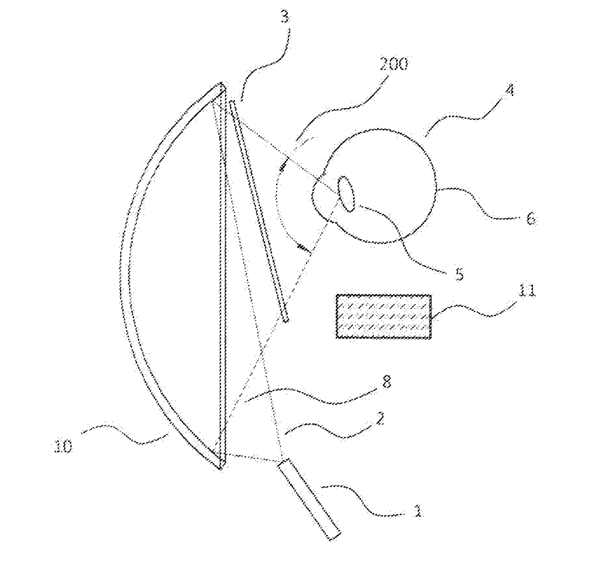
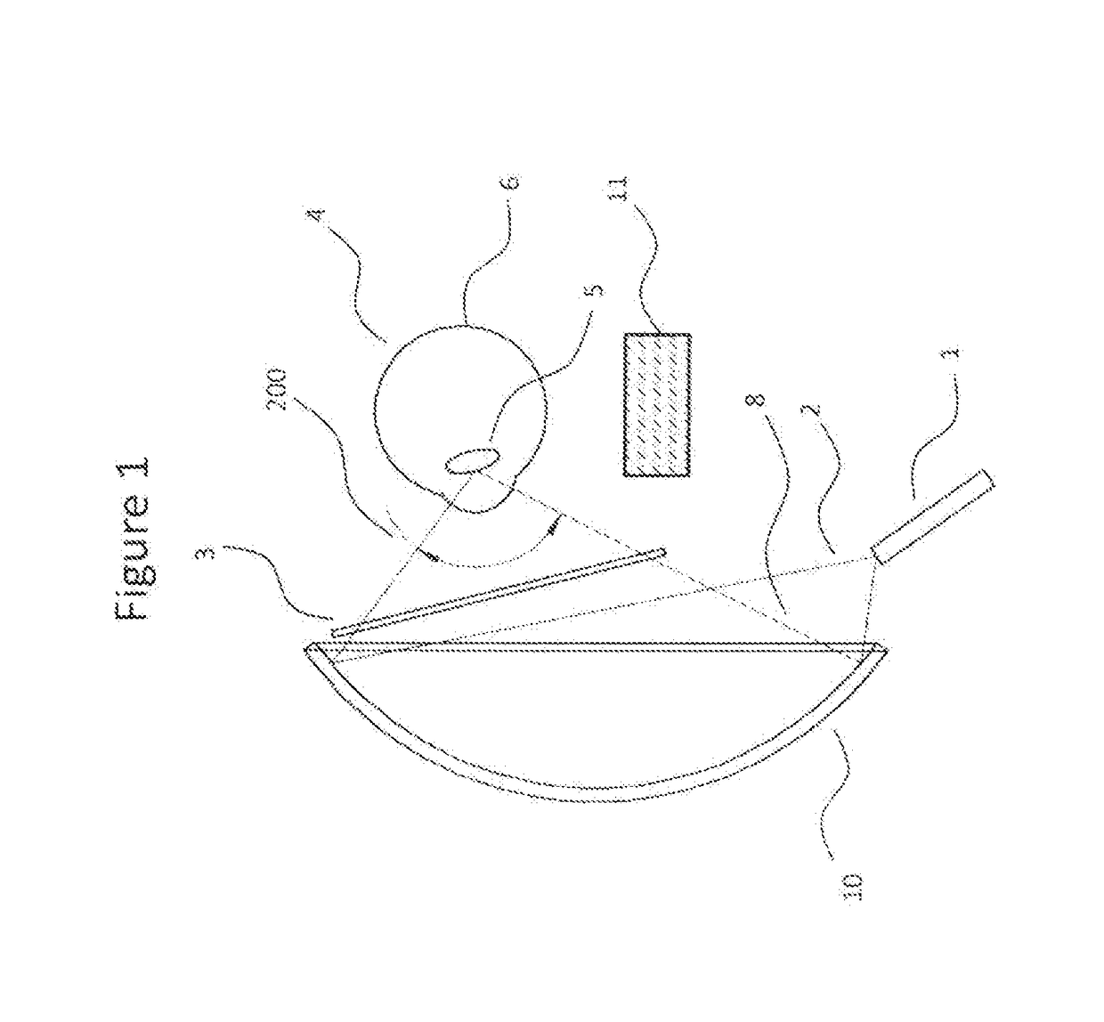
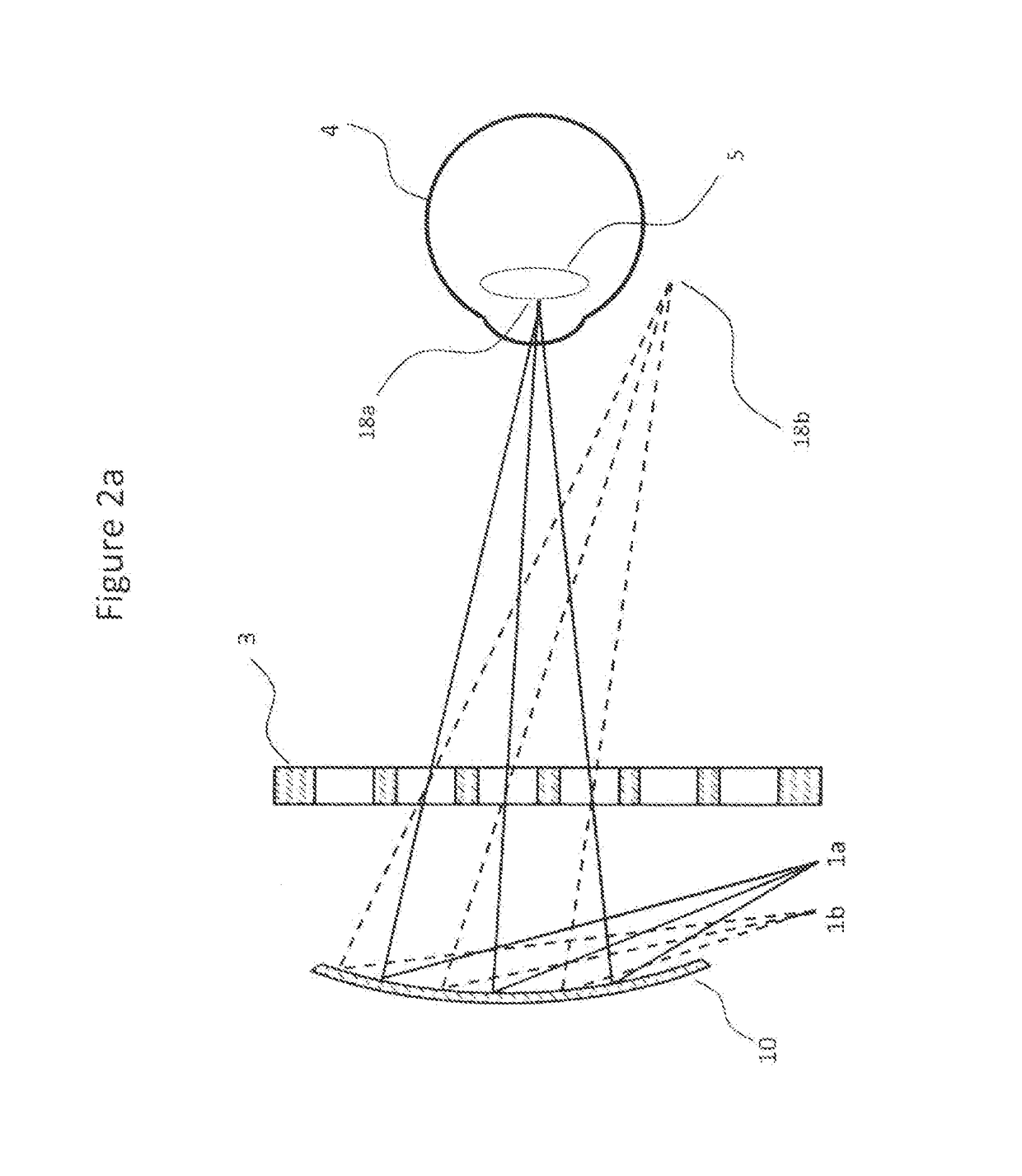
[0083]The first embodiment of this invention is shown in FIGS. 1-3. In exemplary embodiments, a head mounted display device includes a switchable light source that is switched to emit light for generating at least one viewing zone, and a panel illumination unit that is illuminated by the light source. The device further includes an image panel, wherein the panel illumination unit converges the light onto the image panel and the image panel selectively transmits light at different pixels to generate image content. An eye monitor measures information pertaining to an eye configuration of a user wearing the wearable device, wherein the image content is visible to the user when the eye is aligned with respect to the viewing zone. The panel illumination unit converges the light such that light emitted by the image panel converges into the viewing zone positioned based on the eye configuration information measured by the eye monitor.

[0084]FIG. 1 shows the principal optical e...

2nd embodiment

2nd Embodiment

[0095]The second embodiment is shown in FIG. 4, in which a curved image panel 20 is used. The image panel surface could be normal to the converging light. Since liquid crystal technologies often suffer from performance issues when light is incident at a large angle from the panel's surface normal, this configuration would offer advantages in providing better image quality compared to a flat panel.

3rd embodiment

3rd Embodiment

[0096]FIGS. 5a-5b show the third embodiment in which an image panel 31 includes a layer of lens array 32 including a plurality of lenslets located adjacent to the pixel panel, for improved collimation of light emerging from each pixel to limit divergence to further permit close positioning of the image panel relative to the eye. In this embodiment, the pixels 7 (FIG. 5b) in the image panel may have a fill ratio / aperture smaller than regular LCD panels such that light emerging from each pixel may have a high spatial coherence. A micro-lens with size larger than the pixel aperture is positioned closely after each pixel such that light can have an emerging beam with improved collimation. The ratio of the number of micro-lens lenslets to the number of pixels is could be 1:1 (each color pixel has its own private microlens), 1:3 (e.g. red, green, and blue pixel sharing one micro-lens), or other ratios not too large such that the display could remain a high effective resoluti...


PUM


Abstract

A head mounted display device includes a switchable light source that is switched to emit light for generating at least one viewing zone, and a panel illumination unit illuminated by the light source. The panel illumination unit converges the light onto an image panel that selectively transmits light at different pixels to generate image content. An eye monitor measures information pertaining to an eye configuration of a user, and the image content is visible to the user when the eye is aligned with respect to the viewing zone. The panel illumination unit converges the light such that light emitted by the image panel converges into the viewing zone positioned based on the eye configuration information measured by the eye monitor, with limited divergence such that when the display device is worn by the user, the image panel is located at a distance from the user's eye closer than a distance where the eye can focus the pixels.

Description

TECHNICAL FIELD[0001]The invention has application within the field of wearable displays. It is used for achieving a light weight design in head mounted displays.BACKGROUND ART[0002]Head-Mounted-Displays (HMD) is a type of device with increasing popularity within the consumer electronics industry. HMDs, along with similar devices such as helmet-mounted displays, smart glasses, and virtual reality headsets, allow users to wear a display device such that the hardware remains fixed to their heads regardless of the person's movement.[0003]When combined with environmental sensors such as cameras, accelerometers, gyroscopes, compasses, and light meters, HMDs can provide users with experiences in virtual reality and augmented reality. Virtual reality allows a user to be completely submerged into a virtual world where everything the user sees comes from the display device. On the other hand, devices that provide augmented reality allow users to optically see the environment. Images generate...

Claims


Application Information

Patent Timeline
IPC IPC(8): G02B27/01G06F3/01
CPCG02B27/0179G02B27/0172G02B27/0176G06F3/013G02B2027/0112G02B2027/0174G02B2027/013G02B2027/0152G02B2027/0187
Inventor TAM, KA HOMONTGOMERY, DAVID JAMESKAY, ANDREWROBERTS, PETER JOHNZANOLA, MARCO
Owner SHARP KK
Why Eureka
Try Eureka