High frequency signal generation apparatus

a high frequency signal and apparatus technology, applied in the direction of oscillator generators, electrical apparatus, coupling devices, etc., can solve the problems of difficult to manufacture the thz system on the chip, difficult to obtain high output power, and difficult to produce a generator for operating in the high frequency band. achieve the effect of high output power, reduce the area of the apparatus, and high frequency

Active Publication Date: 2017-09-07
KOREA UNIV RES & BUSINESS FOUND
View PDF0 Cites 1 Cited by
  • Summary
  • Abstract
  • Description
  • Claims
  • Application Information

AI Technical Summary

Benefits of technology

[0016]An apparatus for generating a high frequency signal of the invention employs two couplers including a differential generator and a coupler for amplifying a power by adding signals outputted from the two couplers, thereby generating the high frequency signal with high output power with reducing an area of the apparatus.
[0018]The apparatus of the invention may be used in a frequency band where it is impossible to manufacture an amplifier. In addition, a size of the coupler considerably reduces in a high frequency band such as THz, and thus the coupler may be manufactured in on-chip.
[0019]Moreover, two rate-race couplers include respectively the generator and a Wilkinson coupler adds outputs of the two rat-rate couplers, and thus an output power may increase by total four times.

Problems solved by technology

Additionally, it is difficult to manufacture the THz system in on-chip because a passive circuit such as a coupler has very great size, in a lower frequency band.
Highest issue in a THz band is to manufacture a high power signal source.
However, it is difficult to produce a generator for operating in the high frequency band.
It is difficult to produce the generator for operating in the high frequency band, but it is more difficult to obtain high output power.
Since it is difficult to manufacture an amplifier, it is limited to increase the output power by using a power amplifier used in the low frequency band.
Even if the power amplifier for generating a high power might be manufactured, energy efficiency is low because the power amplifier consumes very high DC power.
However, the patent does not disclose a technique for generating a signal having higher output power than the overlapped signal.
Furthermore, the patent does not provide a technique for minimizing a size of an apparatus for generating a high frequency signal.

Method used


Image

  • High frequency signal generation apparatus
  • High frequency signal generation apparatus
  • High frequency signal generation apparatus

Examples


Embodiment Construction

[0027]Example embodiments of the present invention are disclosed herein. However, specific structural and functional details disclosed herein are merely representative for purposes of describing example embodiments of the present invention, however, example embodiments of the present invention may be embodied in many alternate forms and should not be construed as limited to example embodiments of the present invention set forth herein.

[0028]Hereinafter, embodiments of the invention will be described in detail with reference to accompanying drawings. Like numbers refer to like elements throughout the description of the figures.

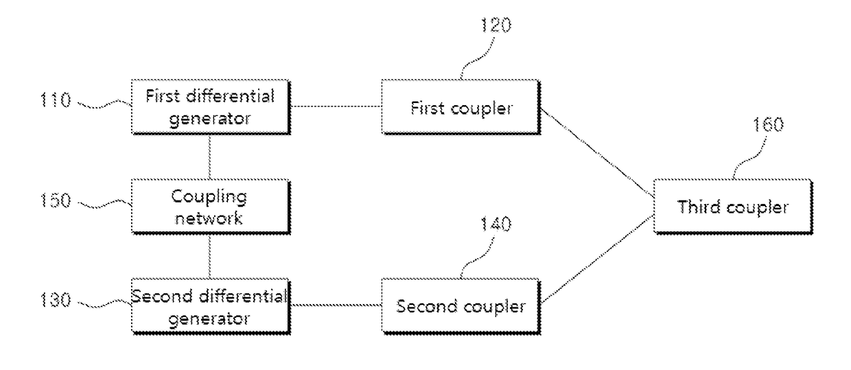
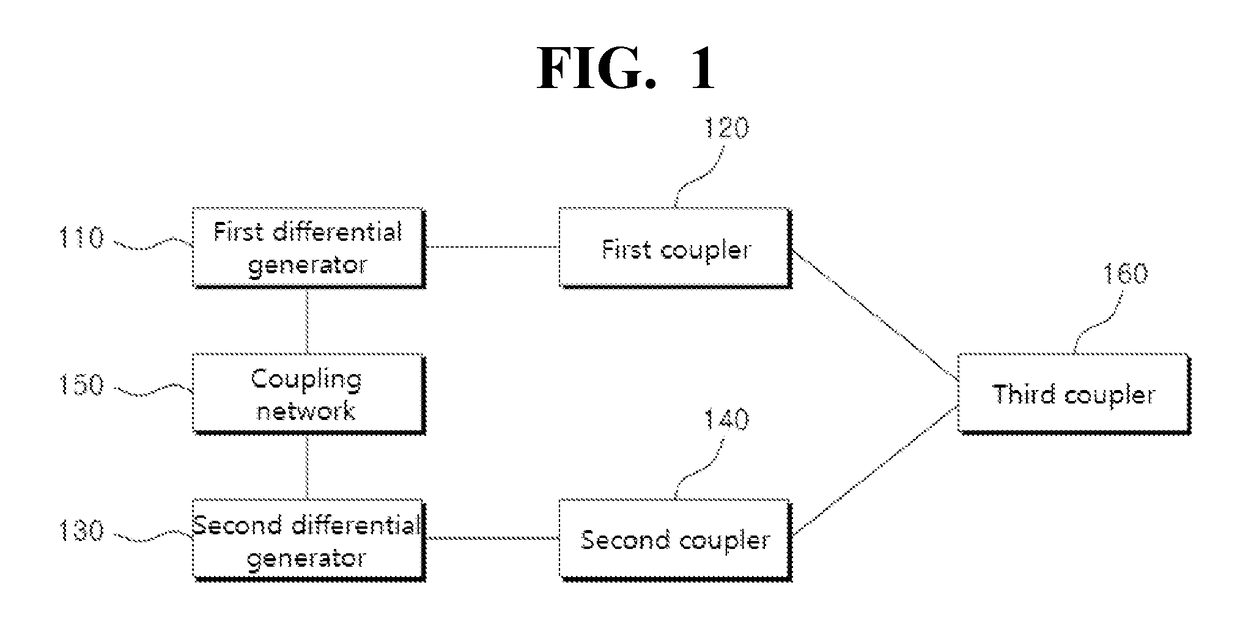
[0029]FIG. 1 is a block diagram illustrating an apparatus for generating a high frequency signal according to one embodiment of the invention.

[0030]In FIG. 1, the apparatus 100 for generating the high frequency signal of the present embodiment may include a first differential generator 110, a first coupler 120, a second differential generator 130, a second coup...


PUM


Abstract

The apparatus comprises a first coupler configured to receive two output signals, having 180° phase difference, outputted from a first differential generator as two input signals, and output a first voltage signal generated by adding the two input signals and a second voltage signal corresponding to subtraction of the two input signals, a second coupler configured to receive two output signals, having 180° phase difference, outputted from a second differential generator as two input signals, and output a third voltage signal generated by adding the two input signals and a fourth voltage signal corresponding to subtraction of the two input signals, a coupling network connected to the first differential generator and the second differential generator and a third coupler configured to output a signal generated by adding the voltage signal outputted from the first coupler and corresponding voltage signal outputted from the second coupler.

Description

BACKGROUND[0001]1. Field of the Invention[0002]The present disclosure relates to an apparatus for generating a high frequency signal, and more particularly relates to an apparatus for generating a high power signal with reducing size of the apparatus.[0003]2. Description of the Related Art[0004]A very high frequency band, for example THz, in the limelight in recent has been required in various application fields such as an imaging or a wideband communication. Importance of a THz system has increased.[0005]It is possible to achieve the THz system driven with small size, low cost and low power due to enhancement of performance of a semiconductor device. Additionally, it is difficult to manufacture the THz system in on-chip because a passive circuit such as a coupler has very great size, in a lower frequency band. However, the THz system can be realized in on-chip in a high frequency band because the passive circuit has small size according as a frequency gets higher.[0006]Highest issu...

Claims


Application Information

Patent Timeline
Patent Type & Authority Applications(United States)
IPC IPC(8): H03B5/12
CPCH03B5/1231H03B5/1212H03B5/1218H03B2200/0076H03D2200/0003H03D2200/0005H03B5/12H01P5/12H03B2200/0084
Inventor RIEH, JAE SUNGYUN, JONG WON
Owner KOREA UNIV RES & BUSINESS FOUND
Why Eureka
Try Eureka