X-ray imaging apparatus

Active Publication Date: 2017-09-14
KONINKLJIJKE PHILIPS NV
View PDF1 Cites 2 Cited by
  • Summary
  • Abstract
  • Description
  • Claims
  • Application Information

AI Technical Summary

Benefits of technology

The patent describes an X-ray imaging apparatus that can track the movement of the X-ray source and align it with the detector to improve image quality. This is achieved without the need for a microcontroller and is relatively simple in configuration. The technical effect is improved image quality and convenience in X-ray imaging.

Problems solved by technology

However, as the mechanical coupling may limit relative motion between the X-ray source and the X-ray detector, the X-ray detector may not follow the rotation of the X-ray source and thus the apparatus cannot be used in those cases where the X-ray source is rotated; meanwhile, in such an apparatus, the height of a table on which a subject is disposed cannot be varied since the X-ray detector is usually attached to the table and thus the table's motion may be limited by the mechanical coupling also.
However, the apparatus needs to incorporate a comparatively complex optical detecting system to sense the position and translation of the X-ray source unit and perform complex computations using the microcontroller to convert the sensed position and translation into a control signal for translating the X-ray detector.

Method used


Image

  • X-ray imaging apparatus
  • X-ray imaging apparatus
  • X-ray imaging apparatus

Examples


Embodiment Construction

[0053]The present invention will be described with respect to particular embodiments and with reference to certain drawings, but the invention is not limited thereto but only by the claims. The drawings described are only schematic and are non-limiting. In the drawings, the size of some of the elements may be exaggerated and not drawn to scale for illustrative purposes.

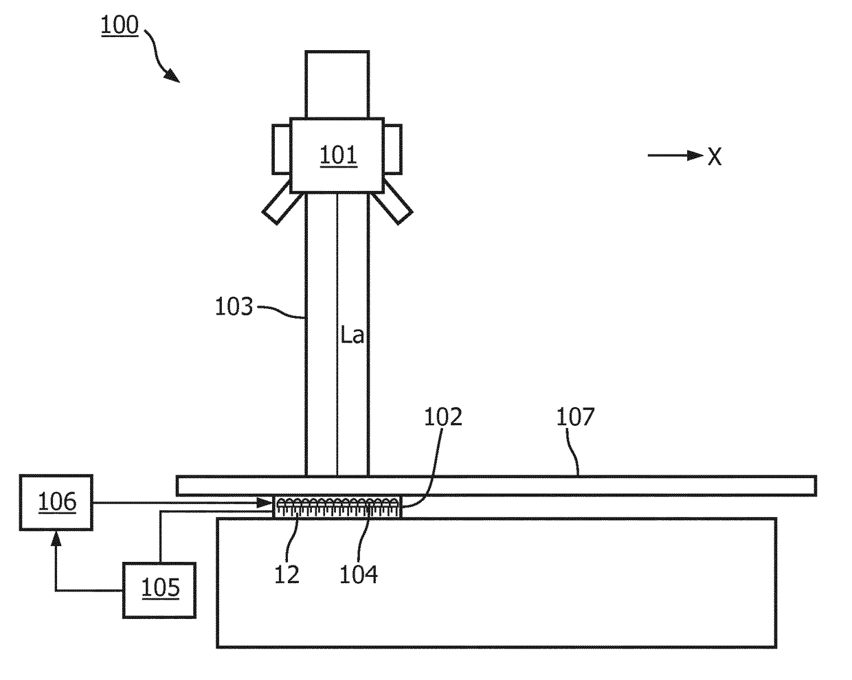
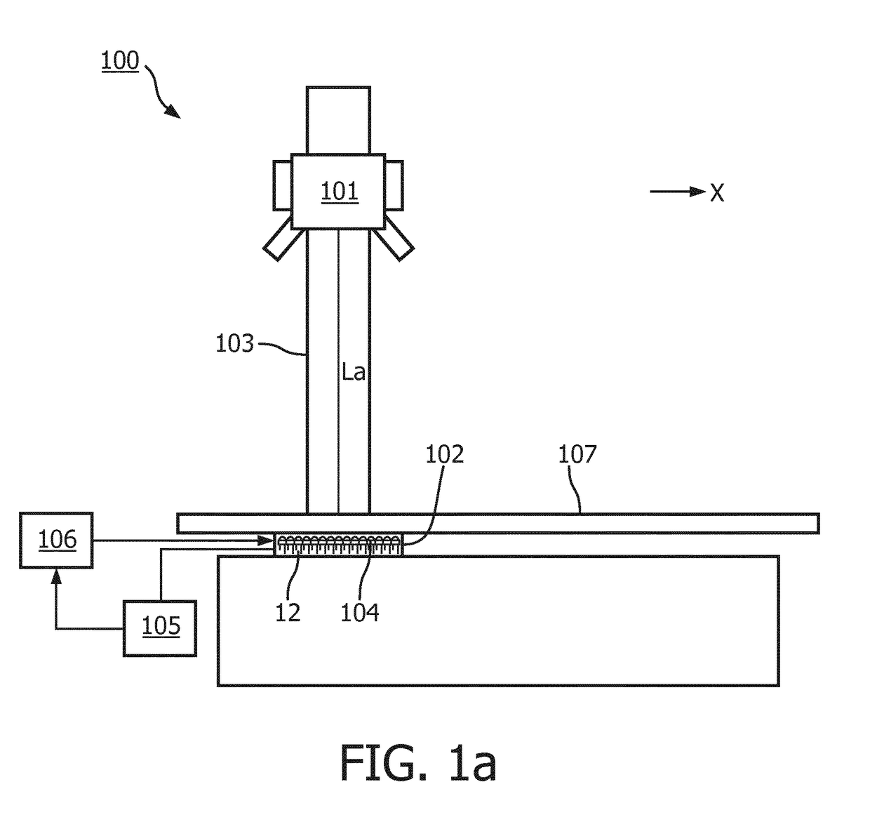
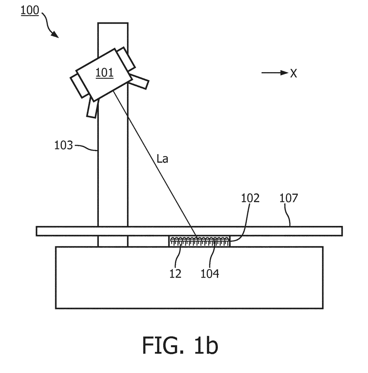
[0054]FIGS. 1a and 1b are schematic representations of an X-ray imaging apparatus 100 according to an embodiment of the present invention. The X-ray imaging apparatus 100 comprises an X-ray source unit 101, an X-ray detecting unit 102, a tube stand 103 and a control unit 105. FIG. 1a also shows a motor 106 which receives a control signal from the control unit 105 to drive the X-ray detecting unit 102 to cause it to move in response to motion of the X-ray source unit 101. Please note that although the control unit 105 and the motor 106 are not shown in FIG. 1b, it may be understood that this is only for simplifying the...


PUM


Abstract

An X-ray imaging apparatus is 100 provided. The X-ray imaging apparatus (100) comprising: an X-ray source unit (101) including an X-ray source for emitting an X-ray beam, the X-ray source unit being movable such that the X-ray beam to be emitted is movable along an axis (X); an X-ray detecting unit (102) comprising an X-ray detector (12) for detecting the X-ray beam, the X-ray detecting unit (102) being movable along the axis (X); and a control unit (105) adapted to control the movement of the X-ray detecting unit (102) in response to a movement of the X-ray source unit (101); wherein the X-ray source unit (101) further includes a laser for emitting a laser beam (La) for indicating a center of the X-ray beam along the axis (X); the X-ray detecting unit (102) further comprises a plurality of sensors (104) arranged along the X-axis (X), each of the plurality of sensors (104) being configured to sense the laser beam (La) and to generate a sensor signal (S, S2, S3, S4, S) indicative of its sensing of the laser beam (La); and the control unit (105) is adapted to control the movement of the X-ray detecting unit (102), based on the sensor signals (S, S2, S3, S4, S) generated by the plurality of sensors.

Description

FIELD OF THE INVENTION[0001]The present invention generally relates to an X-ray imaging apparatus, more particularly to an X-ray imaging apparatus which eliminates the need for conventional mechanical coupling between a detector and an X-ray source.BACKGROUND OF THE INVENTION[0002]During X-ray imaging, it is required that an X-ray detector is always centered with respect to an X-ray beam from an X-ray source. For this reason, a conventional X-ray imaging apparatus may be provided including an X-ray source and an X-ray detector mechanically coupled to each other. Due to the mechanical coupling between the X-ray source and the X-ray detector, the X-ray detector may automatically follow the motion of the X-ray source and thus is always centered with respect to an X-ray beam from the X-ray source. However, as the mechanical coupling may limit relative motion between the X-ray source and the X-ray detector, the X-ray detector may not follow the rotation of the X-ray source and thus the a...

Claims


Application Information

Patent Timeline
IPC IPC(8): A61B6/08A61B6/04A61B6/06A61B6/00
CPCA61B6/08A61B6/547A61B6/4429A61B6/06A61B6/0407
Inventor FU, YAN NING
Owner KONINKLJIJKE PHILIPS NV
Why Eureka
Try Eureka