Container and closure

a container and closure technology, applied in the field of containers, can solve the problems of inability to safely deploy, unstable active agents, waste of process, etc., and achieve the effect of maintaining the sterility of the injection port and safe deploymen

Active Publication Date: 2017-09-14
EULYSIS UK
View PDF6 Cites 12 Cited by
  • Summary
  • Abstract
  • Description
  • Claims
  • Application Information

AI Technical Summary

Benefits of technology

[0034]It may be that the injection port is provided on the end of the hollow piston which is opposite the end which is within the chamber, facing the breakable wall. Said opposite end is pushed by a user in use to cause the piston to slide within the piston guide and break the breakable wall. It may be that said injection port cover covers the injection port on the said opposite end of the piston. It may be that the closure further comprises a removable cap arranged to cover said end of the hollow piston. It may be that the removable cap is also arranged to cover the external surface of the injection port and the injection port cover. The removable cap may thereby restrict (e.g. prevent) manual depression of the hollow piston (until the cap is removed). Accordingly, the closure is safe to transport as the hollow piston may not be accidentally depressed. The removable cap must typically be removed in order for a user to manually depress the hollow piston by applying a manual force to said opposite end of said hollow piston. The user must therefore typically apply a manual force to the injection port covered by the injection port cover. The injection port cover typically maintains sterility of the injection port while the user depresses the hollow piston. In order to extract the contents of the container once the hollow piston has been deployed, the user must typically remove the injection port cover from the injection port. The removable cap and the injection port cover in combination therefore allow the hollow piston to be safely deployed while maintaining the sterility of the injection port.
[0035]The removable cap may be made of a rigid material, for example a rigid plastics material. The removable cap may therefore protect the injection port and the injection port cover.

Problems solved by technology

Such active agents, while stable in vivo, are often found to be unstable when in solution in vitro.
When active agents and diluent are stored in separate containers and then recombined prior to medicinal use, there is then a danger of contamination of the medicament.
Such processes are wasteful, since two containers and two sets of packaging are required for the preparation of one medicament.
However, there are practical and technical problems with the design such that, for example, the frangible seal may be broken during transport and storage or when mishandled by a medical practitioner.
Known vials and vial closures generally require the use of a syringe to extract the recombined contents, limiting their range of use to relatively sterile environments.
The manufacturing process of known vials and vial closures can be complex and is not suited to large scale mechanisation.

Method used


Image

  • Container and closure
  • Container and closure
  • Container and closure

Examples


Embodiment Construction

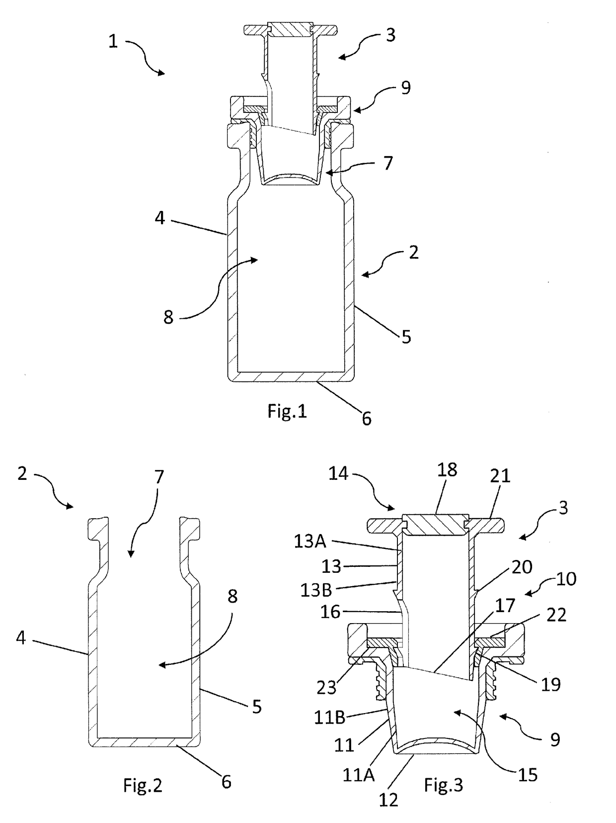
[0075]A container 1 for use in dispensing one or more active agents as shown in FIG. 1 comprises a vial 2 and a vial closure 3. The vial 2, as shown in FIG. 2, comprises a vial body 4 comprising a generally cylindrical side wall 5 extending upwards from a generally circular base 6. A generally cylindrical opening 7 is provided opposite said circular base 6. Together the base 6 and the cylindrical side wall 7 define an internal vial chamber 8. The vial body 4 is made from glass or plastics, or any other suitable material.

[0076]The vial closure 3, as shown in FIG. 3, comprises a vial closure body 9 and a vial closure lid 10. The vial closure body 9 comprises a generally cylindrical closure wall 11 dimensioned and configured for an interference fit within the opening 7 of the vial body 4 when the vial closure 3 is fully inserted into said opening 7. The closure wall 11 is typically made of a resilient plastics material. A generally circular closure base 12 extends across the end of the...


PUM

PropertyMeasurementUnit
areaaaaaaaaaaa
solutionaaaaaaaaaa
structuresaaaaaaaaaa

Abstract

A closure for dispensing one or more active agents into a container comprises a sealed or sealable chamber having a breakable wall and a hollow piston slidably mounted in a piston guide. Said hollow piston comprises an outer wall having an end in the chamber and at least one ventilation aperture. Said end has a cutting formation. Said hollow piston is slidable in the piston guide between a ventilation position in which the at least one ventilation aperture allows ventilation of the chamber and a sealed position in which the at least one ventilation aperture is sealed to prevent ventilation of the chamber and a deployed position in which the cutting formation has broken through at least a portion of the breakable wall. The outer wall has a retaining formation which engages with the piston guide to releasably resist sliding of the hollow piston between the ventilation position and the sealed position and the deployed position. The hollow piston may have an outer wall, and said outer wall has an end within the chamber, facing the breakable wall, wherein the cutting end has a first edge having a cutting formation and a gap in said cutting formation.

Description

FIELD OF THE INVENTION[0001]The invention relates to the field of containers with a dry active agent, a liquid diluent and a mechanism for combining the two before use, as well as claims for closures for such containers, and methods of manufacturing such containers and closures retaining dry active agents and liquid diluents.BACKGROUND TO THE INVENTION[0002]In the fields of biochemistry and medicine it is common to use active biological species in solution. Such active agents, while stable in vivo, are often found to be unstable when in solution in vitro. In such cases, it is preferable to store the active agents separately from any solvent. Dry agents may be recombined with a diluent immediately before use such that active properties do not have time to degrade. Examples of such active biological agents include proteins, enzymes, nucleic acid sequences and vaccines, which are used medicinally as, for example, oncology treatments, antibiotics, treatments for human immunodeficiency v...

Claims


Application Information

Patent Timeline
Patent Type & Authority Applications(United States)
IPC IPC(8): A61J1/20A61K9/08A61K38/00A61K38/43A61K39/00B65D51/28A61J1/14A61M11/00B65B29/10B65B7/28B65B55/02B65B63/08B01L3/00A61K9/00
CPCA61J1/2072B01L2300/0672A61K9/08A61K38/00A61K38/43A61K39/00A61K9/0019A61J1/1412A61J1/2027A61J1/2093A61M11/00A61J1/2096B65B29/10B65B7/28B65B55/02B65B63/08B65D51/2835B01L2200/141B01L2300/042B01L2300/043B01L2300/044B01L2300/047B01L2300/048B01L3/523A61J1/2075A61J1/1406B01L3/502B65D51/002B65D51/241B65D51/2814A61J1/1425A61J1/1431B01L2400/0683A61J1/14A61J1/20B01L3/00B65D47/36B65D51/24B65D51/28
Inventor TSAKAS, SPYRIDON EDOUARDTSAKAS, SPYRIDON CHRISTOS
Owner EULYSIS UK
Why Eureka
Try Eureka