
Systems for petroleum wastewater treatment including removable coalescer components and related methods

a technology of petroleum wastewater and coalescing structure, which is applied in the direction of water/sewage treatment by degassing, separation process, and waste water treatment from quaries, etc., can solve the problems of significant capital expense, inability to easily and easily replace existing coalescing structures within such induced gas floatation tanks, and inability to easily and easily remove coalescing structures

Active Publication Date: 2017-09-14
PURESTREAM SERVICES
View PDF2 Cites 2 Cited by
  • Summary
  • Abstract
  • Description
  • Claims
  • Application Information

AI Technical Summary

Benefits of technology

The patent text is about a device that helps to separate liquids from gases. The device has a section where the liquid flows through and gets separated from the gas. This section has special devices that help bring the liquid together and make it flow smoothly. The devices are mounted on a shaft and can rotate as the liquid flows through them. This makes sure that the liquid flows through the device in the best way possible and all the gas is removed. The device is designed in a way that prevents the liquid from flowing around the device, which would make it difficult to separate the carbon dioxide from the liquid. This invention helps to separate liquids from gases more effectively.

Problems solved by technology

For example, existing coalescing structures within such induced gas floatation tanks are not readily and easily removable, particularly once the coalescer structure becomes fouled.
In addition, the plurality of such individual coalescing members may be far less expensive than existing coalescer structures, where replacement represents a significant capital expense.

Method used


Image

  • Systems for petroleum wastewater treatment including removable coalescer components and related methods
  • Systems for petroleum wastewater treatment including removable coalescer components and related methods
  • Systems for petroleum wastewater treatment including removable coalescer components and related methods

Examples


Embodiment Construction

[0027]I. Introduction

[0028]Before describing various embodiments of the present disclosure in detail, it is to be understood that this disclosure is not limited to the parameters of the particularly exemplified systems, methods, and / or products, which may, of course, vary. Thus, while certain embodiments of the present disclosure will be described in detail, with reference to specific configurations, parameters, features (e.g., components, members, elements, parts, and / or portions), etc., the descriptions are illustrative and are not to be construed as limiting the scope of the claimed invention. In addition, the terminology used herein is for the purpose of describing the embodiments, and is not necessarily intended to limit the scope of the claimed invention.

[0029]Unless defined otherwise, all technical and scientific terms used herein have the same meaning as commonly understood by one of ordinary skill in the art to which the present disclosure pertains.

[0030]Various aspects of ...


PUM

PropertyMeasurementUnit
Fractionaaaaaaaaaa
Fractionaaaaaaaaaa
Fractionaaaaaaaaaa

Abstract

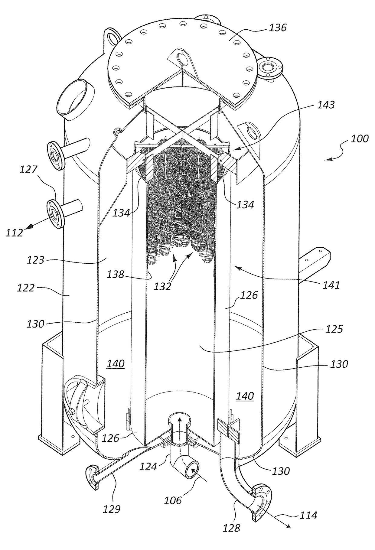
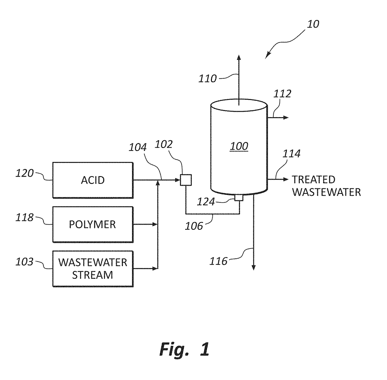
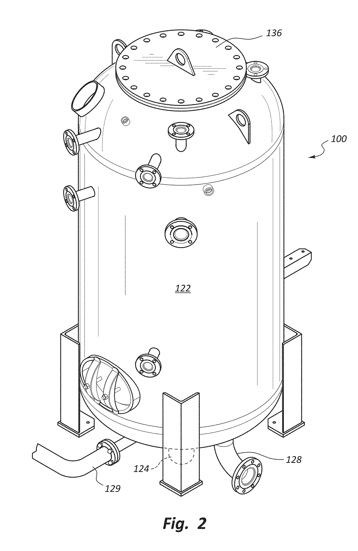
Apparatus for removing suspended impurities from a liquid (e.g., wastewater), methods of use, and systems including such apparatus. In an embodiment, an apparatus may include a vessel defining a chamber for receiving gas induced liquid influent through an inlet, the influent including suspended impurities. A riser tube may be provided within the vessel, in fluid communication with the inlet so that liquid influent introduced into the vessel through the inlet is introduced into the riser tube. One or more coalescing members may be disposed within the riser tube. The coalescing members may be sufficiently small to be easily removable by hand, without requiring a crane. The coalescing members may be freely disposed within the riser tube, rotatable within the flow of the liquid influent, aiding the coalescing members in exhibiting some degree of “self-cleaning”, so as to be less prone to fouling and clogging.

Description

CROSS-REFERENCE TO RELATED APPLICATIONS[0001]Not applicable.BACKGROUND OF THE INVENTION[0002]1. The Field of the Invention[0003]The present invention relates to wastewater treatment systems and methods that are useful in treating wastewater, e.g., as derived or employed in oil and / or gas exploration, drilling, and production.[0004]2. The Relevant Technology[0005]As natural gas is extracted from a ground well, a significant quantity of water often accompanies the natural gas. This water is typically separated from the natural gas at a location proximate to the well head and then stored in an adjacent tank. Because of contaminants within the water, the water is typically trucked to a licensed disposal facility where it is deposited in a lined pond for evaporation. This same operation also typically occurs in the context of oil wells. That is, a significant quantity of water will often accompany extracted oil. Such water may also often be present where hydraulic fracturing (i.e., “frac...

Claims


Application Information

Patent Timeline
IPC IPC(8): C02F1/52B01D21/00C02F1/66C02F1/20C02F1/24
CPCC02F1/52C02F1/20C02F1/24C02F2101/322B01D21/0069C02F2101/32C02F2103/10C02F1/66B01D17/0211B01D17/045C02F1/40
Inventor JAHN, CHRISTOPHERSOCHALSKI, CHRISTOPHERCRUZ, BILLY
Owner PURESTREAM SERVICES
Learn More