Petroleum wastewater recycling apparatus
A technology of waste liquid recovery and equipment, applied in the field of petroleum production, can solve the problems of high pressure in the tank, large odor of waste lye, difficult treatment, etc., and achieve the effects of increasing efficiency, reducing danger and simple structure
- Summary
- Abstract
- Description
- Claims
- Application Information
AI Technical Summary
Problems solved by technology
Method used
Image
Examples
Embodiment 1
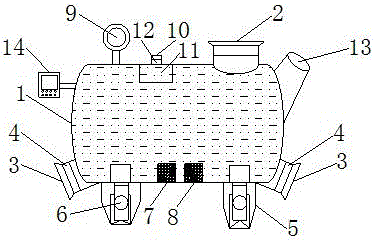
[0019] This example provides figure 1 The petroleum waste liquid recovery equipment shown includes a liquid storage tank 1, the liquid storage tank 1 is hinged to the electric telescopic column 6 through a hinge buckle, the electric telescopic column 6 is fixedly connected to the support leg 5, and the electric telescopic column 6 is fixedly connected to the supporting leg 5. The telescopic column 6 is electrically connected to the PLC controller 14, and the liquid storage tank 1 is provided with a pressure sensor 7 and a liquid level sensor 8, and the pressure sensor 7 and the liquid level sensor 8 are respectively electrically connected to the PLC controller 14, The right side of the top of the liquid storage tank 1 is provided with a liquid inlet 2, and the other side of the liquid storage tank 1 is provided with a pressure gauge 9, the pressure gauge 9 is electrically connected to the pressure sensor 7, and the liquid inlet A pressure relief port 10 is provided between the...
Embodiment 2
[0028] This embodiment provides a petroleum waste liquid recovery device, the structure of which includes a liquid storage tank 1, the liquid storage tank 1 is hinged to the electric telescopic column 6 through a hinge buckle, and the electric telescopic column 6 is fixedly connected to the support leg 5 , the electric telescopic column 6 is electrically connected with the PLC controller 14, the pressure sensor 7 and the liquid level sensor 8 are arranged in the liquid storage tank 1, and the pressure sensor 7 and the liquid level sensor 8 are respectively connected with the PLC controller 14 Electrically connected, the right side of the top of the liquid storage tank 1 is provided with a liquid inlet 2, and the other side of the liquid storage tank 1 is provided with a pressure gauge 9, and the pressure gauge 9 is electrically connected to the pressure sensor 7, A pressure relief port 10 is provided between the liquid inlet 2 and the pressure gauge 9, and an automatic ventilat...
Embodiment 3
[0038] A petroleum waste liquid recovery device in this embodiment is structurally the same as in Embodiments 1 and 2. The difference is that in this embodiment, the adsorption medium balls are formed by uniformly mixing and drying the following parts by weight: particles Vermiculite with a diameter of 1-2 mm, 2 parts; fly ash ceramsite with a particle size of 1-3 mm, 20 parts; zeolite with a particle size of 2-4 mm, 30 parts; activated carbon with a particle size of 2-4 mm, 10 parts parts; diatomaceous earth, 5 parts.
[0039] Specifically, in this example, the adsorption medium balls are made of the following parts by weight after uniform mixing and drying: vermiculite with a particle size of 1-2mm, 2g; fly ash ceramsite with a particle size of 1-3mm, 20g; zeolite with a particle size of 2-4mm, 30g; activated carbon with a particle size of 2-4mm, 10g; diatomaceous earth, 5g.
PUM
| Property | Measurement | Unit |
|---|---|---|
| particle diameter | aaaaa | aaaaa |
| particle diameter | aaaaa | aaaaa |
| particle diameter | aaaaa | aaaaa |
Abstract
Description
Claims
Application Information
 - R&D
- Intellectual Property
- Life Sciences
- Materials
- Tech Scout
- Unparalleled Data Quality
- Higher Quality Content
- 60% Fewer Hallucinations
Browse by: Latest US Patents, China's latest patents, Technical Efficacy Thesaurus, Application Domain, Technology Topic, Popular Technical Reports.
© 2025 PatSnap. All rights reserved.Legal|Privacy policy|Modern Slavery Act Transparency Statement|Sitemap|About US| Contact US: help@patsnap.com

