Supercharge Your Innovation With Domain-Expert AI Agents!

Overhead camshaft engine

a camshaft engine and camshaft technology, applied in the direction of valve drives, machines/engines, drip or splash lubrication, etc., can solve the problems of reducing affecting the stiffness of the crankshaft, and the difficulty of assembling the engin

Active Publication Date: 2017-09-14
HONDA MOTOR CO LTD
View PDF6 Cites 3 Cited by
  • Summary
  • Abstract
  • Description
  • Claims
  • Application Information

AI Technical Summary

Benefits of technology

The goal of this patent is to create an overhead camshaft engine that has a stiffer crankshaft, simplifies the cooling system, and simplifies the engine's structure without making it more difficult to assemble.

Problems solved by technology

However, the crankcase is required to be made of relatively stiff member, and the assembling of the engine may not be as easy as wished.
Also, because the crankshaft pulley for transmitting the power of the crankshaft to the cam mechanism via a timing belt is positioned on the part of the crankshaft located inward of the second bearing, the distance between the two bearings is increased by the width of this crankshaft pulley, and this is detrimental in maximizing the stiffness of the crankshaft.
Also, the positioning of the timing belt complicates the cooling system of the engine.

Method used


Image

  • Overhead camshaft engine
  • Overhead camshaft engine
  • Overhead camshaft engine

Examples


Embodiment Construction

)

[0030]A preferred embodiment of the present invention is described in the following with reference to FIGS. 1 to 6.

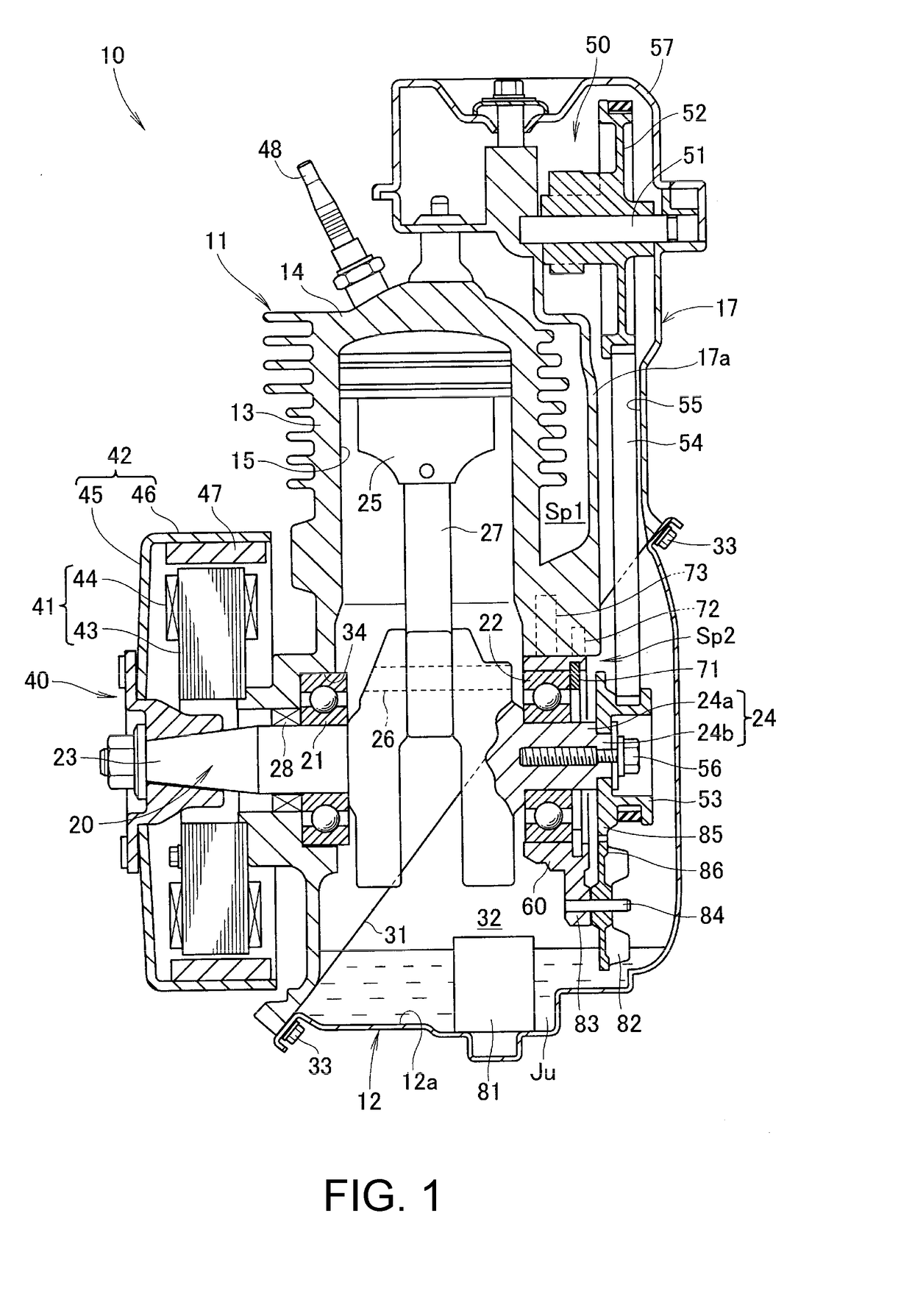
[0031]Referring to FIG. 1, the engine 10 of the illustrated embodiment includes a cylinder block 11 which integrally combines a cylinder head part 14 and a cylinder block part 13 which are formed as separate component parts in a more conventional arrangement, and internally defines a cylinder 15 therein. This engine 10 consists of a single cylinder, air cooled engine, and is provided with air cooling fins 16 on an outer periphery of the cylinder block part 13.

[0032]The cylinder block 11 further includes a belt cover part 17 extending sideways (rightward in FIG. 1) and upward in the shape of letter L when seen from sideways, and internally defines a belt chamber 55. The upper end of the belt chamber 55 is closed by a head cover 57 attached to an upper end of the belt cover part 17 to define a cam actuating mechanism chamber 50. A camshaft pulley 52 is rotatably supporte...


PUM


Abstract

The overhead camshaft engine (10) includes a cylinder block (11), a crankcase (12) attached to a lower part of the cylinder block to define a crankcase chamber (32), a bearing retaining member (60) attached to a part of the cylinder block, a crankshaft (20) rotatably supported by a pair of bearings (21, 22) supported by the cylinder block and the bearing retaining member, respectively, and a crankshaft pulley (53) attached to a part of the end of the crankshaft projecting outward from the bearing supported by the bearing retaining member.

Description

TECHNICAL FIELD[0001]The present invention relates to an improved overhead camshaft engine.BACKGROUND ART[0002]There is a desire to form an engine main body defining a cylinder and a crankcase chamber by using as small a number of component parts as possible, and support the crankshaft of the engine in a favorable manner in terms of structural integrity and ease of assembly. In a known overhead camshaft engine disclosed in JP2002-349340A, the engine main body includes a cylinder block that is integrally formed with a cylinder head, and a first bearing for supporting a first end of the crankshaft is fitted into a hole formed in the cylinder block. The lower end of the cylinder block is defined by a plane extending obliquely across the crankshaft, and a crankcase having a corresponding upper end is attached to the lower end of the cylinder block to define the crankcase chamber in cooperation with the cylinder block. The crankcase is formed with a hole, and a second bearing for support...

Claims


Application Information

Patent Timeline
IPC IPC(8): F01L1/053F02B75/16F01P1/02F01L1/02F02F1/00
CPCF01L1/053F01L1/024F01L2001/0476F01P1/02F02B75/16F02F1/002F02B67/06F02F7/0021F02F7/0043F02F7/0053F02F7/007F02F7/0073F02F7/0004F01M9/06F02F2007/0078
Inventor KONO, SHOHEI
Owner HONDA MOTOR CO LTD
Features
  • R&D
  • Intellectual Property
  • Life Sciences
  • Materials
  • Tech Scout
  • Unparalleled Data Quality
  • Higher Quality Content
  • 60% Fewer Hallucinations
Learn More