Automatic washing machine and control method

a washing machine and automatic technology, applied in the field of washing machines, can solve the problems of large noise and vibration generated during the washing process, inability to completely control the noise and vibration, and the whole effect of noise and vibration control is not ideal, so as to improve transmission efficiency and stability, space and cost are saved, and the installation structure is simple.

Active Publication Date: 2017-09-21
QINGDAO HAIER WASHING MASCH CO LTD
View PDF8 Cites 13 Cited by
  • Summary
  • Abstract
  • Description
  • Claims
  • Application Information

AI Technical Summary

Benefits of technology

[0030]The washing machine of the present disclosure uses two rotors to respectively drive the inner tub and the pulsator to rotate. Although the deceleration mechanism is used on the rotor that drives the pulsator to rotate, the transmission efficiency and the stability are improved compared with the existing speed reduction distribution system using one input power and two outputs. In addition, since the use of washing and dehydration conditions conversion clutch, space and cost are still saved, and the installation structure is simple, the weight and the volume of the drive system are reduced to some extent. Since the deceleration clutch device is eliminated, the control of the present disclosure is more convenient, the washing and dehydration process conversion is stable.
[0031]The scheme of the present disclosure has an effect of reducing energy consumption compared with the scheme of the dual-rotor direct driving the inner tub and the pulsator. After a long period of testing it is found that the two rotors of the direct drive motor

Problems solved by technology

And that increases the instability of the entire system, the noise and vibration generated during the washing process are relatively large.
Therefore, the whole effect of noise and vibration control is not too ideal.
The structure of the motor built-in electromagnetic clutch structure is complex, high cost and short service life.
If the water level is low, it is difficult to lift the floating clutch mechanism.
However, it also has the following defects after several experiments: as the best working range for the direct drive motor driving rotor is 600-800 rev/min, the energy consumption is relatively low in this range.
If the rotor r

Method used


Image

  • Automatic washing machine and control method
  • Automatic washing machine and control method
  • Automatic washing machine and control method

Examples


embodiment 1

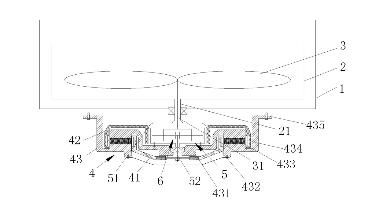
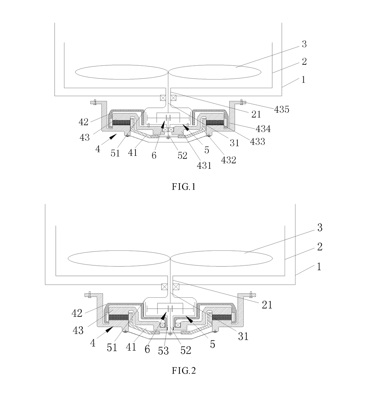
[0038]As shown in FIG. 1 and FIG. 2, the deceleration mechanism 5 of the present embodiment comprises a rotatable housing 51, a gear mechanism 6 arranged in the housing 51, an inner tub shaft 21, a pulsator shaft 31 and an input shaft 52. The housing 51 and the gear mechanism 6 rotate relatively independently. The inner tub shaft 21 is a sleeve structure, one end of which is connected to the inner tub 2, and the other end thereof is connected to the housing 51. The housing 51 is connected with the rotor 42. The pulsator shaft 31 is coaxially disposed in the inner tub shaft 21, one end is connected to the pulsator 3, and the other end is connected with a power output end of the gear mechanism 6. One end of the input shaft 52 is connected to the rotor 41 and the other end thereof is connected to the power input end of the gear mechanism 6.

[0039]The two rotors of the direct drive motor 4 are respectively an inner rotor 41 and an outer rotor 42. The stator 43 is a disc-shaped structure ...

embodiment 2

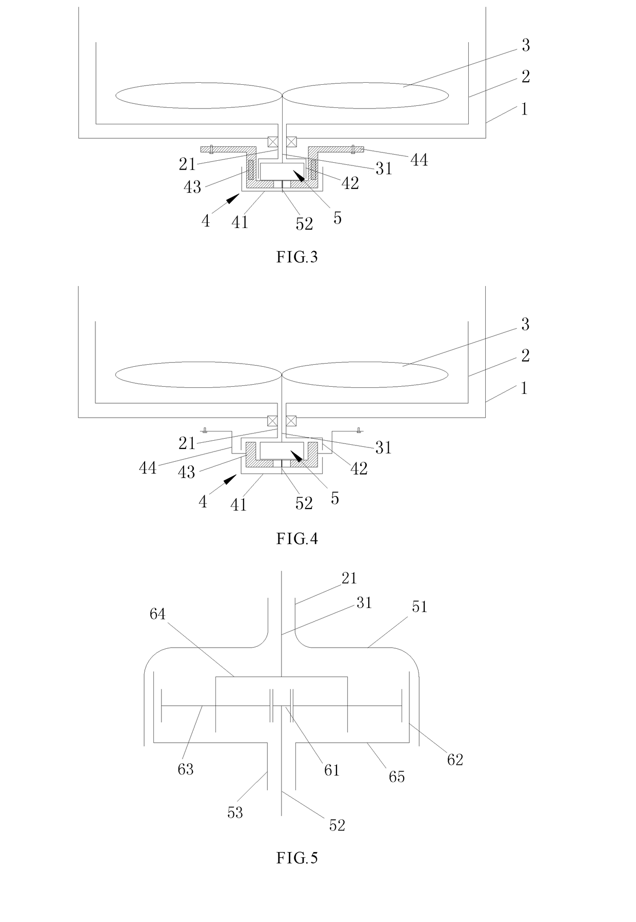
[0040]As shown in FIG. 5, the gear mechanism 6 of the deceleration mechanism of the present embodiment comprises a sun gear 61, an internal ring gear 62 and a planetary gear 62 meshing with the sun gear 61 and the internal ring gear 62 respectively. The sun gear 61 is mounted on the input shaft 52. A plurality of planetary gears 63 are provided and which are mounted on a planet wheel carrier 64, and the planet wheel carrier 64 is connected with the pulsator shaft 31. A lower end of the internal ring gear 62 is provided with a lower end cover 65, the lower end cover 65 is directly connected with an upper surface of the stator 43. (see FIG. 1). Or the lower end cover is connected with an input sleeve 53, the input sleeve 53 is arranged outside of the input shaft 52, and the input sleeve 53 is spline-connected with the stator 43.

[0041]A reduction ratio of the deceleration mechanism is in a range from 1 / 10 to 1 / 2, the reduction ratio of 1 / 5 is taken as an example, and the deceleration m...

embodiment 3

[0042]As shown in FIG. 6, the gear mechanism 6 of the deceleration mechanism comprises a central gear 66, an internal ring gear 62 and a transmission gear 67 meshing with the central gear 66 and the internal ring gear 62 respectively. The central gear 66 is mounted on the input shaft 52, the internal ring gear 62 is connected with the pulsator shaft 31, the transmission gear 67 is mounted on a lower end cover 65 through a gear shaft, and the lower end cover 65 is connected directly to an upper surface of the stator 43 (see FIG. 1). Or, the lower end cover is connected to an input sleeve 53, the input sleeve 53 is arranged outside the input shaft 52, and the input sleeve 53 is spline-connected with the stator 43 (see FIG. 2).

[0043]The deceleration mechanism with the reduction ratio of 1 / 6 is taken as an example, in combination with the direct drive motor 4 of the embodiment 1. During the washing process, the inner rotor 1 rotates forward at a speed of 600 rev / min, and the input shaft...


PUM


Abstract

A washing machine comprises an outer tub, an inner tub, a pulsator and a driving means having two rotors, a stator and a deceleration mechanism. One rotor drives the pulsator, and the other rotor drives the inner tub. During washing, the two rotors drive the pulsator and the inner tub to rotate in the same or opposite directions, and during dehydration, the pulsator and the inner tub rotate in the same direction and at the same speed. The automatic washing machine saves on energy consumption, has stable output and has high transmission efficiency.

Description

FIELD OF THE INVENTION[0001]The present disclosure relates to a washing machine, more particularly to a fully automatic washing machine and a control method for driving a pulsator and an inner tub to rotate by using a double rotor direct drive motor.BACKGROUND OF THE INVENTION[0002]The rotation of pulsator and inner tub of a traditional pulsator washing machine is driven by a deceleration clutch to which a motor drives a belt through a pulley to transmit power. The deceleration clutch through its internal gear structure, transforms the motor's high speed rotation into a lower speed rotation which is required in different washing process of the washing machine. At the same time, according to different washing methods, the deceleration clutch uses different gear structure which transmits different rotation directions and rotation modes to the pulsator.[0003]Because the deceleration clutch and the motor are laterally arranged at the bottom of the outer tub, the whole system structure i...

Claims


Application Information

Patent Timeline
IPC IPC(8): D06F37/40H02K7/116H02K16/02D06F17/08D06F37/30
CPCD06F37/40D06F17/08H02K7/116H02K16/02D06F37/304
Inventor LV, PEISHIXU, SHENGYANG, LIN
Owner QINGDAO HAIER WASHING MASCH CO LTD
Why Eureka
Try Eureka