Energy return orthotic systems

Active Publication Date: 2017-09-28
SUBIOMED INC
View PDF19 Cites 6 Cited by
  • Summary
  • Abstract
  • Description
  • Claims
  • Application Information

AI Technical Summary

Benefits of technology

[0018]In some aspects, the platform could create an inverse wave to oppose the natural rise and fall of pressure during the gait cycle thus leveling pressures and reducing the need for motion induced by the normal forces of the gait cycle.
[0019]In some aspects th

Problems solved by technology

Such impact energy frequently causes physical damage leading to injury, in particular injury of the foot.
However, conventional devices are not dynamic as designed.
Conventional orthotic devices typically include a shimmed, rigid post and as a result, dynamic adjustments to the foot during the gait cycle cannot be done.
For example, adjustments such as making the foot tip out further, making the foot tip in further, raising the heel, raising the ball of the foot, and the like cannot be accomplished with conventional devices

Method used


Image

  • Energy return orthotic systems
  • Energy return orthotic systems
  • Energy return orthotic systems

Examples


first embodiment

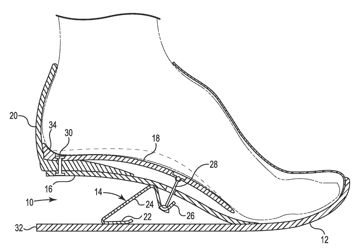
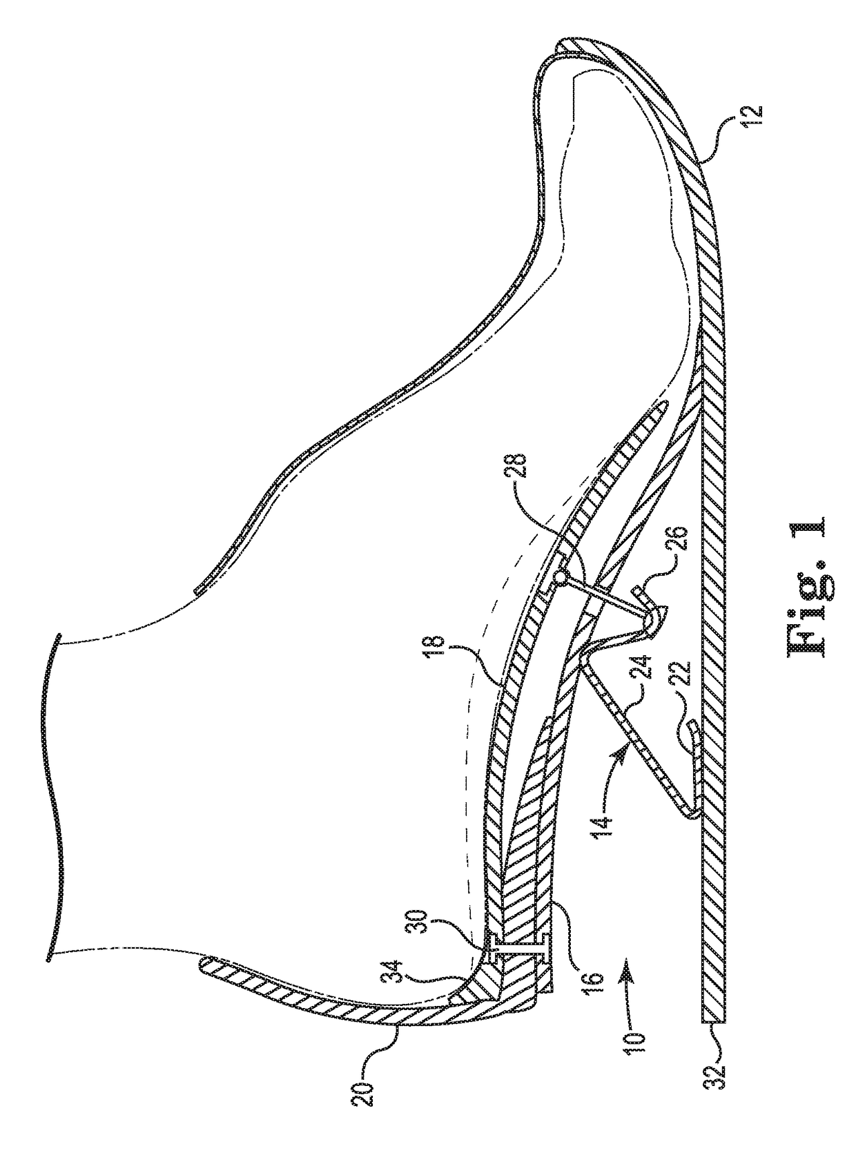
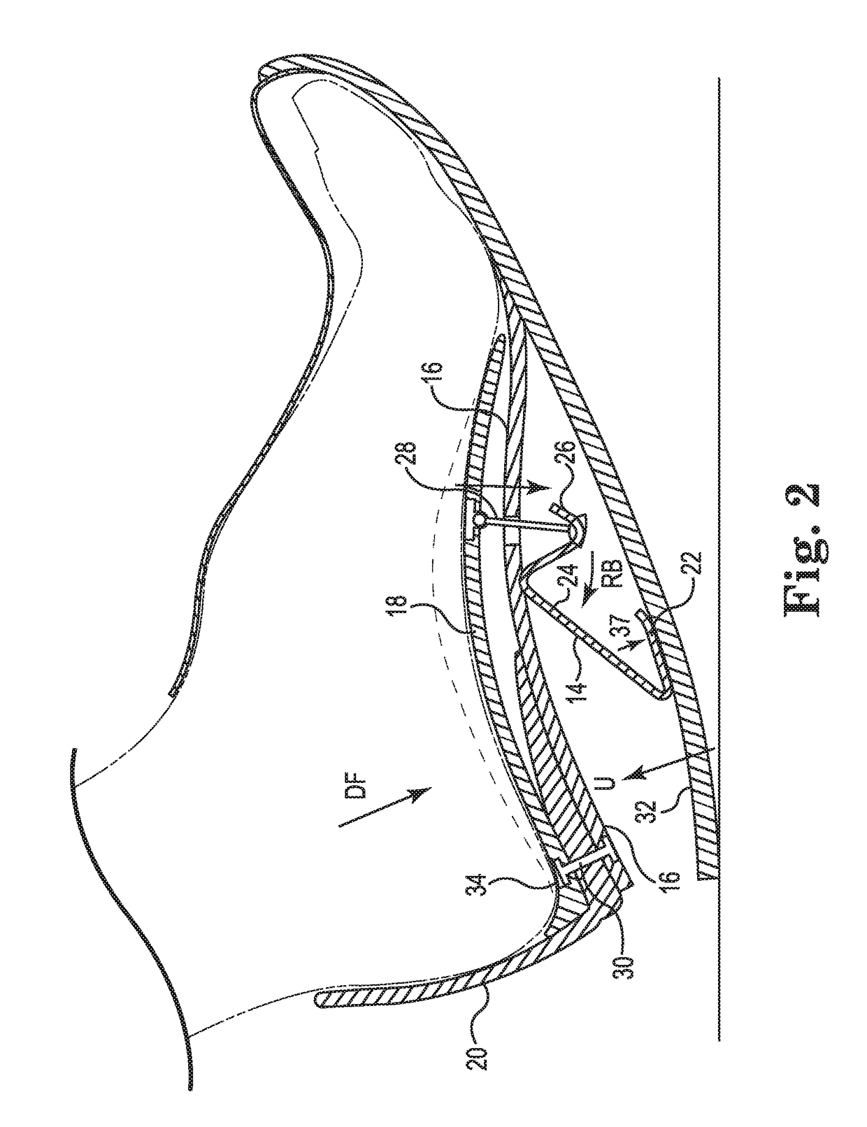
[0106]Referring now to FIGS. 1 through 6, the orthotic energy return system in accordance with the invention is depicted. FIG. 1 illustrates a foot (in phantom lines) at rest wearing the energy return system 10 in accordance with the invention. The energy return system 10 is shown in the unburdened or off-loaded position with the base layer 12 at rest on a surface such as the ground. The energy return system 10 broadly includes base layer 12, lever 14, platen 16 and orthotic 18. Base 12 may be of any length so long as it generally extends from the sole of the foot to the toe region. Base 12 may comprise any material used for the soles of shoes including but not limited to rubber, plastics, polymers, polyurethanes and the like. Lever 14 includes slide 22, angled central portion 24 and angled connecting portion 26. Lever 14 is made from a material that is resilient to allow it to dynamically deform during the gait cycle. Suitable materials that may be utilized for lever 14 include pla...

embodiment 2010

[0141]FIG. 19 depicts a fourth alternative embodiment 2010 of the energy return system with the foot depicted in a static unburdened position. Like elements are labeled with like numerals. Particularly, orthotic 2018 is attached to platen 2016 at the rear of the foot 2020. Base 2012 is attached to platen 2016 underneath the ball of the foot 2029. Band 2011 surrounds the phalanges and the cable 2028 is attached to the band. As platen 2016 flattens, lever 2014 functions to drawn arch up U. Orthotic 2018 moves rearward R and upward U against the arch when downward force is applied to the ground during the gait cycle. This embodiment is designed to treat plantar fascia.

[0142]FIGS. 20 and 21 depict a fifth alternative embodiment 2110 of the energy return system in accordance with the invention designed to treat plantar fasciitis. Like elements are labeled with like numerals. Base 2112 is attached to platen 2116 behind heel at 2120. As best seen in FIG. 21, orthotic 2118 is modified to fo...


PUM


Abstract

A plurality of orthotic systems are provided. One bi-layer system is constructed from a single sheet of fabric that is molded into two layers. One tri-layer system includes a base layer; a mid-layer; and an upper layer. The upper layer is joined to the mid-layer and the mid-layer is joined to the base layer. The coupling of the base layer, the mid-layer and the upper layer create a rear spring section, a mid-spring section and a front spring section in which the upper layer is suspended over the mid-layer and the heel portion is suspended on the proximal heel end of the base layer.

Description

RELATED APPLICATION DATA[0001]This application is a continuation-in-part of U.S. application Ser. No. 14 / 742,208, filed on Jun. 17, 2015, which is a continuation of U.S. application Ser. No. 13 / 827,949, filed Mar. 14, 2013, now U.S. Pat. No. 9,066,559, which claims priority to U.S. provisional application Ser. No. 61 / 707,344, filed on Sep. 28, 2012, and U.S. provisional application Ser. No. 61 / 665,097, filed Jun. 27, 2012; the entireties of which are incorporated herein by reference.FIELD OF THE INVENTION[0002]The invention relates generally to orthotic systems that are configured to absorb energy and return it to an individual wearer's foot.BACKGROUND OF THE RELATED ART[0003]Walking and running can be defined as methods of locomotion involving the use of the two legs, alternately, to provide both support and propulsion, with at least one foot being in contact with the ground at all times. While the teams gait and walking are often used interchangeably, the word gait refers to the m...

Claims


Application Information

Patent Timeline
IPC IPC(8): A43B7/28A43B13/18A43B7/24A43B7/14A43B13/38
CPCA43B7/142A43B7/149A43B13/181A43B7/141A43B13/183A43B7/14A43B13/386A43B7/28A43B7/24A43B13/184A43B7/143A43B7/1445A43B7/146A43B17/006
Inventor BUTLER, BARRY A.
Owner SUBIOMED INC
Why Eureka
Try Eureka