
Optical tracking system and coordinate registration method for optical tracking system

a tracking system and optical tracking technology, applied in the field of optical tracking systems and coordinate registration methods can solve the problems of reducing accuracy and reliability, affecting the accuracy of optical tracking systems, and requiring substantial time and cost for manufacturing stamps, so as to achieve accurate and easy operation, substantial time and cost, and the effect of reducing the cos

Active Publication Date: 2017-09-28
KOHYOUNG TECH
View PDF0 Cites 9 Cited by
  • Summary
  • Abstract
  • Description
  • Claims
  • Application Information

AI Technical Summary

Benefits of technology

This patent describes an optical tracking system that can accurately and easily track a patient or surgical instrument in a shorter time and at a reduced cost. The system can be easily re-performed to account for any movement or changes in the patient's posture. This helps to alleviate pain and side effects for the patient and reduces the time and cost associated with manufacturing and preparing the system for surgery. Overall, this patent provides a solution to the technical problems in the related art.

Problems solved by technology

However, the conventional methods above suffer from a variety of problems such as the difficulty involved in attaching the marker, side effects caused by implanting the marker in the bone, a reduction in accuracy and reliability attributable to the change in the marker position which may be generated when the marker is bitten by teeth, inconvenience in manufacturing an expensive STAMP before a surgery and the substantial time and cost required for manufacturing the STAMP, etc.
Moreover, in the case of the conventional methods, even when the DRB is strictly fixed to a patient, if the patient moves, the distance between the DRB and the lesion of the patient or the posture of the patient may change.
Thus, accurate tracking cannot be carried out and re-registration cannot be performed, thereby resulting in a problem that the DRB cannot be used.
Thus, it is difficult to carry out the tracking in a substantially accurate manner.

Method used


Image

  • Optical tracking system and coordinate registration method for optical tracking system
  • Optical tracking system and coordinate registration method for optical tracking system
  • Optical tracking system and coordinate registration method for optical tracking system

Examples


Embodiment Construction

[0035]The present disclosure may be diversely modified and may have various forms. Specific embodiments will be illustrated in the drawings and will be described in detail. However, this is not intended to limit the present disclosure to specific forms of disclosure. It is to be understood that the present disclosure includes all modifications, equivalents and substitutions which fall within the spirit and technical scope of the present disclosure.

[0036]The terms “first” and “second” may be used for describing various components. However, the components shall not be limited by these terms. These terms are used only for the purpose of distinguishing one component from another component. For example, a first component may be named as a second component without departing from the scope of rights of the present disclosure. Similarly, a second component may be named as a first component.

[0037]The terms used herein are merely used to describe specific embodiments and are not intended to l...


PUM


Abstract

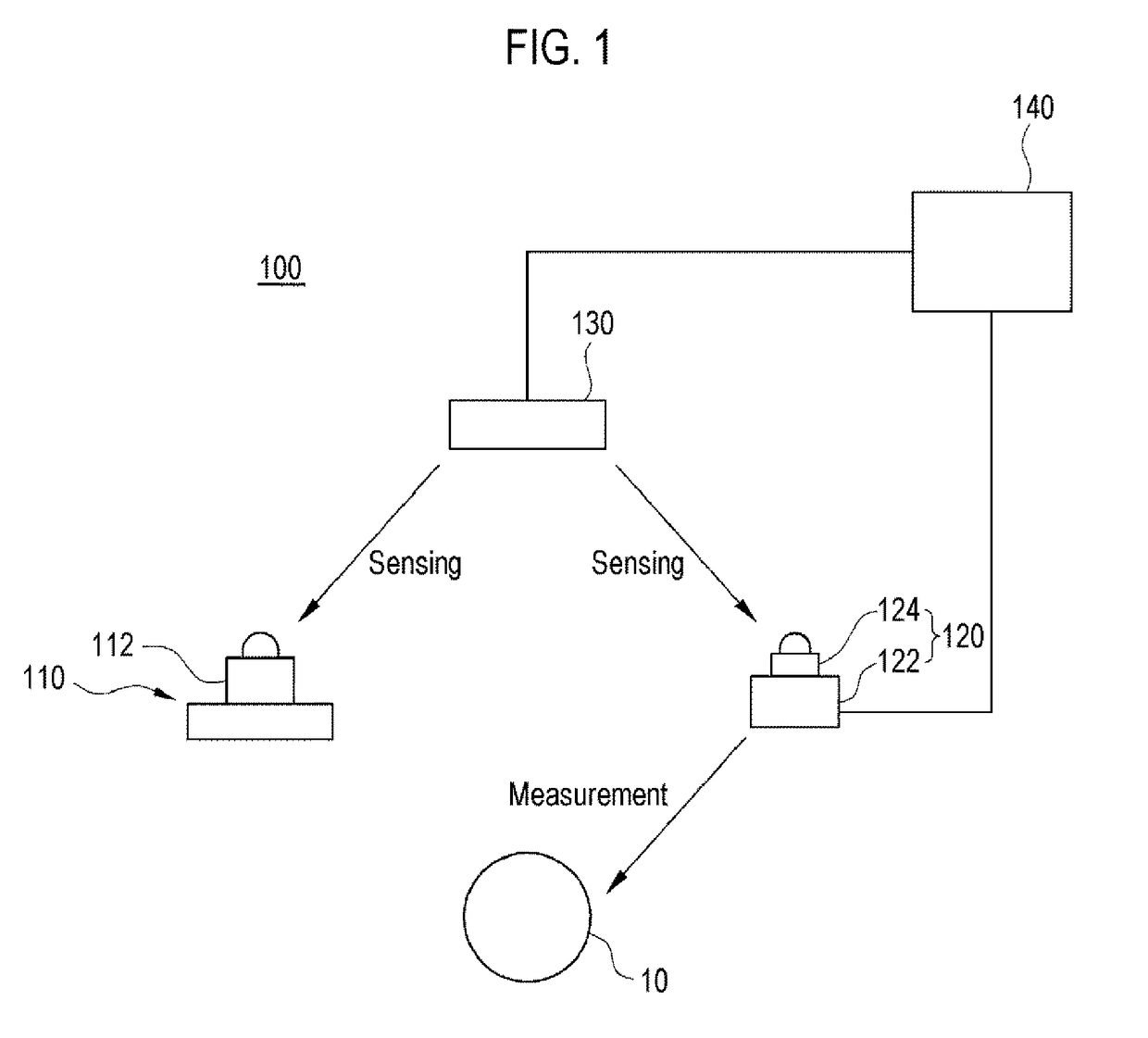
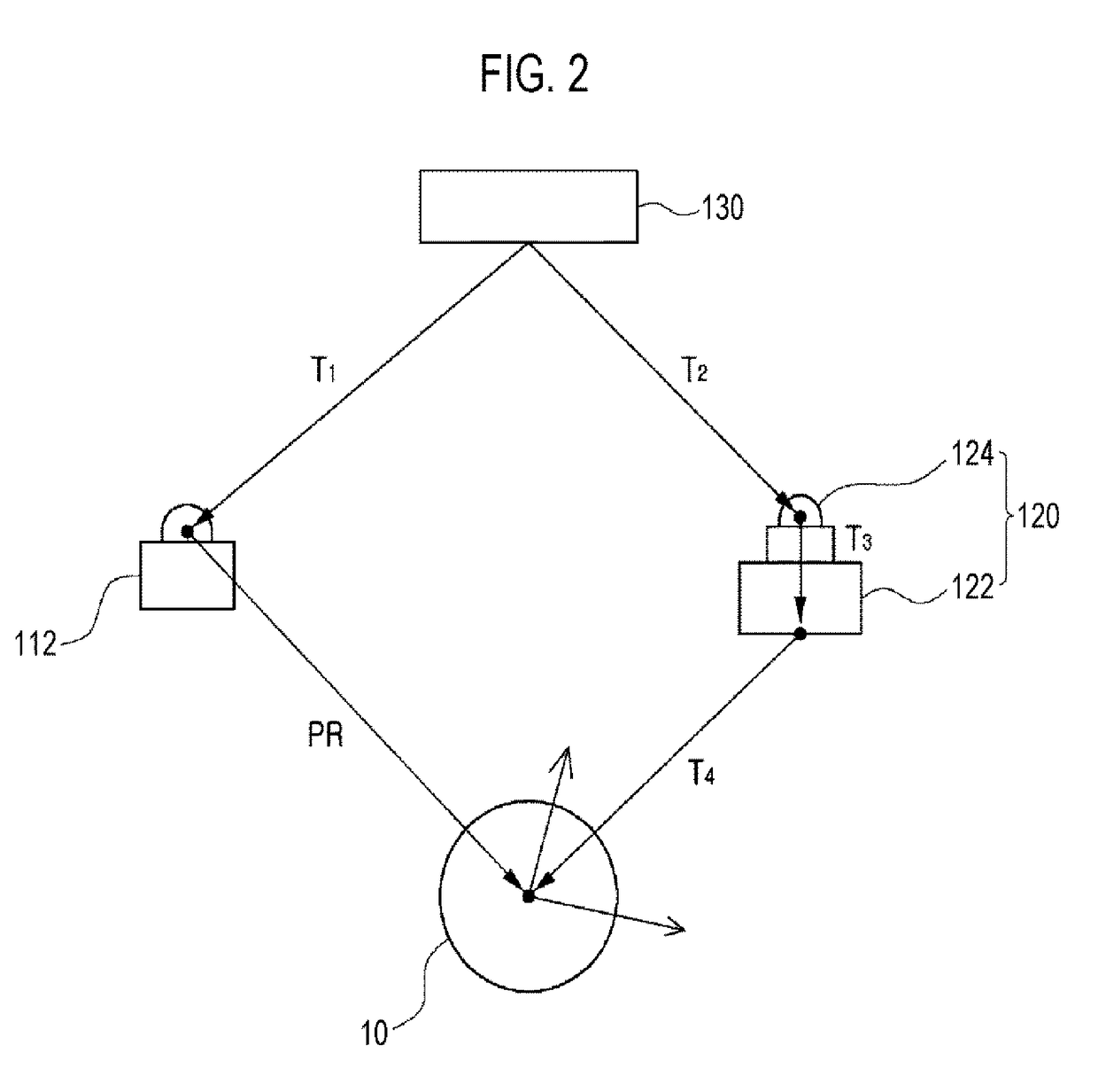
An optical tracking system may comprise a reference marker unit stationarily disposed relative to a patient, a shape measurement unit configured to measure the three-dimensional shape of a specified part of the patient corresponding to a three-dimensional image, a tracking sensor unit configured to sense the reference marker unit and the shape measurement unit, and a processing unit. The processing unit may acquire a coordinate transformation relationship between the reference marker unit and the tracking sensor unit and a coordinate transformation relationship between the shape measurement unit and the tracking sensor unit based on a sensing result of the tracking sensor unit, acquire a coordinate transformation relationship between the specified part of the patient and the shape measurement unit based on a measurement result of the shape measurement unit, and define a coordinate system of the patient relative to the reference marker unit from the acquired coordinate transformation relationships.

Description

TECHNICAL FIELD[0001]The present disclosure relates to an optical tracking system and a coordinate registration method for an optical tracking system and, more particularly, to an optical tracking system for tracking a patient or a surgical instrument and a coordinate registration method for an optical tracking system for tracking a patient or a surgical instrument.[0002]The present disclosure was derived from studies carried out as part of the industrial source technology development project of the Ministry of Knowledge Economy of Republic of Korea [Assignment specific number: 10040097, Assignment name: Development of technology on minimally-invasive multiple-degree-of-freedom surgical robot system for medical surgical robot video-based otolaryngology operation and neurosurgery operation].BACKGROUND ART[0003]Recently, in a surgery for treating a lesion of a patient, an image-guided surgery using a pre-captured image is widely utilized. In particular, when a surgery is to be perform...

Claims


Application Information

Patent Timeline
Patent Type & Authority Applications(United States)
IPC IPC(8): A61B5/06A61B34/20A61B90/00G01B11/00
CPCA61B5/06G01B11/002A61B2034/2057A61B90/36A61B2034/2046A61B34/20A61B2090/373A61B2034/2055A61B2090/365A61B34/30A61B34/74A61B90/00A61B90/90G06T7/292A61B17/00A61B17/00234A61B2034/2068
Inventor LEE, HYUN KI
Owner KOHYOUNG TECH
Learn More