Prosthetic Valve System and Methods for Transluminal Delivery

a technology of prosthetic valves and deployment systems, applied in the field of prosthetic cardiac valves and related deployment systems, can solve the problems of complex complexes, complicated recovery, and prolonged patient hospitalization, and achieve the effects of avoiding substantial migration of the prosthetic valve assembly, eliminating problems, and optimizing function and durability

US20170273785A1Inactive Publication Date: 2017-09-28MEDTRONIC COREVALVE
3 Cites 3 Cited by

Patent Information

Authority / Receiving Office
US · United States
Patent Type
Applications(United States)
Current Assignee / Owner
Publication Date
2017-09-28
Estimated Expiration
Not applicable · inactive patent

Smart Images

  • Figure 1
    Figure 1
  • Figure 2
    Figure 2
  • Figure 3
    Figure 3
Patent Text Reader

Abstract

A prosthetic valve assembly for use in replacing a deficient native valve comprises a replacement valve supported on an expandable prosthesis frame. If desired, one or more expandable anchors may be used. The prosthesis frame, which entirely supports the valve annulus, valve leaflets, and valve commissure points, is configured to be collapsible for transluminal delivery and expandable to contact the anatomical annulus of the native valve when the assembly is properly positioned. Portions of the prosthesis frame may expand to a preset diameter to maintain coaptivity of the replacement valve and to prevent occlusion of the coronary ostia. The prosthesis frame is compressible about a catheter, and restrained from expanding by an outer sheath. The catheter may be inserted inside a lumen within the body, such as the femoral artery, and delivered to a desired location, such as the heart. When the outer sheath is retracted, the prosthesis frame expands to an expanded position such that the valve and prosthesis frame expand at the implantation site and the anchor engages the lumen wall. The prosthesis frame has a non-cylindrical configuration with a preset maximum expansion diameter region about the valve opening to maintain the preferred valve geometry. The prosthesis frame may also have other regions having a preset maximum expansion diameter to avoid blockage of adjacent structures such as the coronary ostia.
Need to check novelty before this filing date? Find Prior Art

Description

CROSS-REFERENCE TO RELATED APPLICATIONS

[0001] The present application A) claims priority under 35 U.S.C. §119(e) to U.S. Provisional Application No. 60 / 684,192 filed on May 24, 2005, and B) is a continuation-in-part of U.S. Ser. No. 10 / 772,101 filed on Feb. 4, 2004, which is a continuation-in-part of U.S. Ser. No. 10 / 412,634 filed on Apr. 10, 2003, now U.S. Pat. No. 7,018,406, which is a continuation-in-part of U.S. Ser. No. 10 / 130,355, now U.S. Pat. No. 6,830,584, which is the U.S. national phase under §371 of International Application No. PCT / FR00 / 03176, filed on Nov. 15, 2000, which was published in a language other than English and which claimed priority from French Application No. 99 / 14462 filed on Nov. 17, 1999, now French Patent No. 2,800,984, herein incorporated by reference in their entirety.FIELD OF THE INVENTION

[0002] The present invention relates to a prosthetic cardiac valve and related deployment system that can be delivered percutaneously through the vasculature, and a ...

Examples

Embodiment Construction

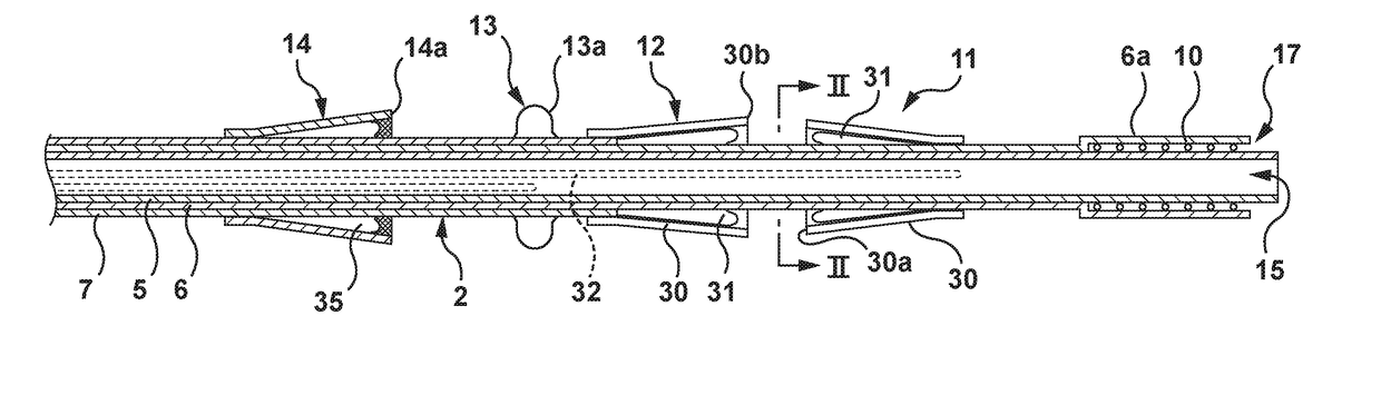
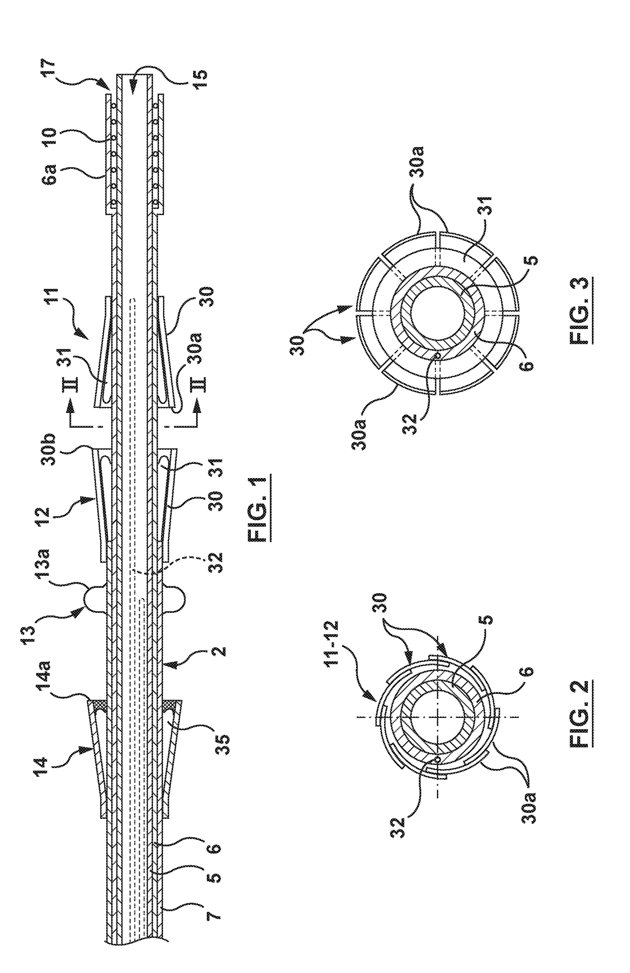
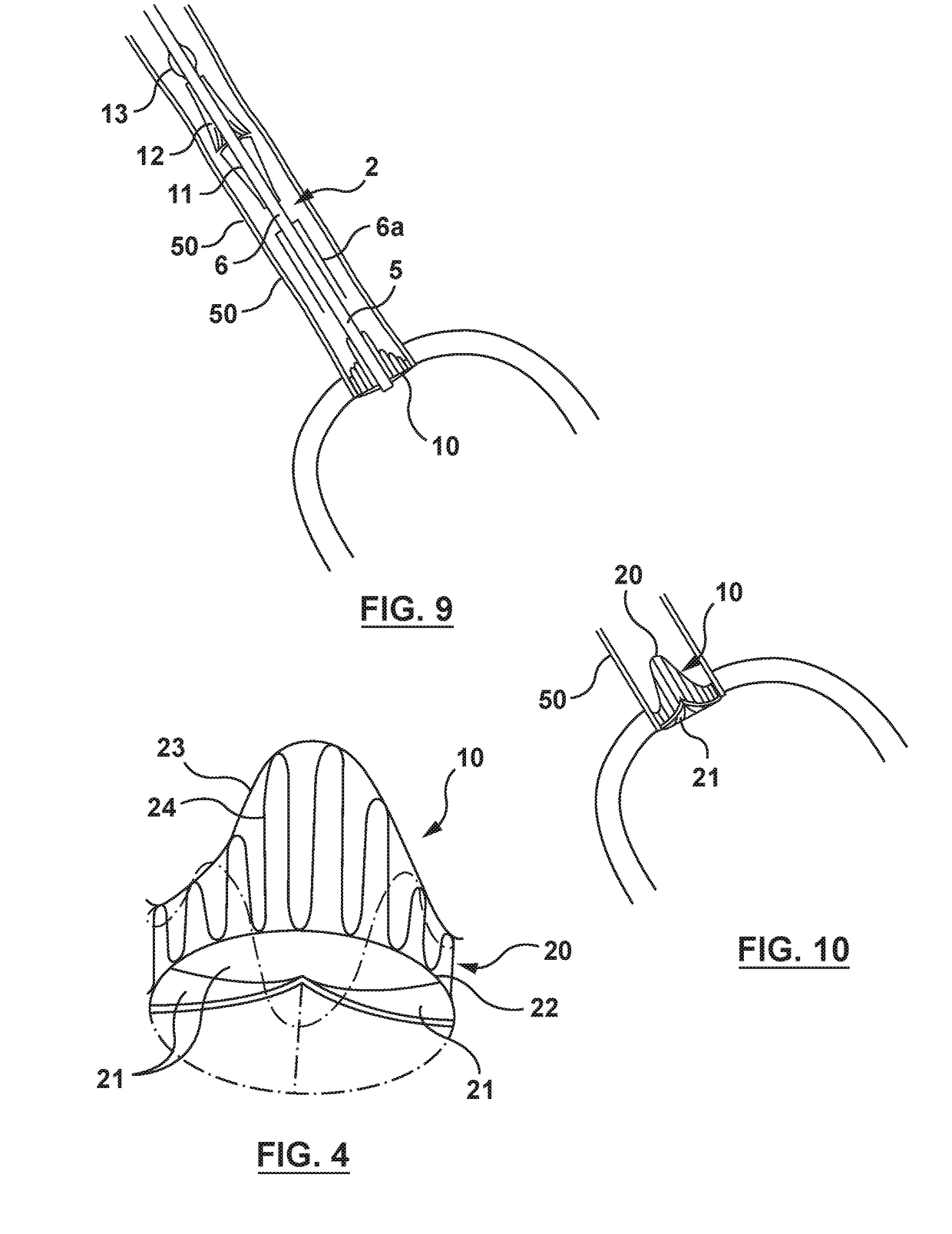
[0136]Reference is now made to the figures wherein like parts are designated with like numerals throughout. FIGS. 1 to 3 represent a device 1 for replacing a heart valve by a percutaneous route. This device comprises a tubular catheter 2 formed from three tubes 5, 6, 7 engaged one inside the other and on which there are placed, from the proximal end to the distal end (considered with respect to the flow of blood, that is to say from right to left in FIG. 1), a prosthetic valve 10, two series of blades 11, 12, a balloon 13 and a filter 14. The three tubes 5, 6, 7 are mounted so that they can slide one inside the other. The interior tube 5 delimits a passage 15, the cross section of which is large enough to allow blood to flow through it. At the proximal end, the intermediate tube 6 forms a bell housing 6a delimiting, with the interior tube 5, an annular cavity 17 in which the prosthetic valve 10 is contained in the furled condition.

[0137]FIG. 4 shows that this valve 10 comprises an a...