Gas jetting apparatus for film formation apparatus

a film formation apparatus and gas jetting technology, which is applied in the direction of chemistry apparatus and processes, coatings, chemical/physical processes, etc., can solve the problems of difficult to obtain a high density, difficult to achieve a high density, and large amount of radical gas sources,

Active Publication Date: 2017-09-28
TOSHIBA MITSUBISHI-ELECTRIC IND SYST CORP
View PDF3 Cites 2 Cited by
  • Summary
  • Abstract
  • Description
  • Claims
  • Application Information

AI Technical Summary

Benefits of technology

[0030]A gas jetting apparatus for a film formation apparatus, according to the present invention includes a gas supply unit for supplying a gas, a gas dispersion supply unit for accepting the gas supplied from the gas supply unit, and a gas jetting cell unit for accepting the gas dispersed in the gas dispersion supply unit, rectifying the gas, and jetting the rectified gas into the film formation apparatus. The gas jetting cell unit has a fan shape internally formed with a gap serving as a gas route. The gas in the gas dispersion supply unit enters from a wider-width side of the fan shape into the gap, and, due to the fan shape, the gas is rectified, accelerated, and output from a narrower-width side of the fan shape into the film formation apparatus.
[0031]Therefore, a gas passed through the gap in the gas jetting cell unit can be rectified in a predetermined direction, accelerated, output, and jetted as a gas in a beam shape having directivity from the gas jetting apparatus. Therefore, the gas jetting apparatus according to the present invention can uniformly jet, even onto a treatment-target object having a high-aspect-ratio groove, the gas into the groove, and, as a result, a uniform film can be formed in the groove.

Problems solved by technology

Therefore, the treatment-target object is often damaged by the plasma (ions and electrons), thus a performance of a semiconductor function has been significantly lowered.
However, in the film formation treatment, it is difficult to obtain a high density, large amount radical gas source, and, as a result, a film formation requires an extremely longer period of time.
However, the shortened period of time is limited, thus significant improvement in film formation has been difficult.

Method used


Image

  • Gas jetting apparatus for film formation apparatus
  • Gas jetting apparatus for film formation apparatus
  • Gas jetting apparatus for film formation apparatus

Examples


first exemplary embodiment

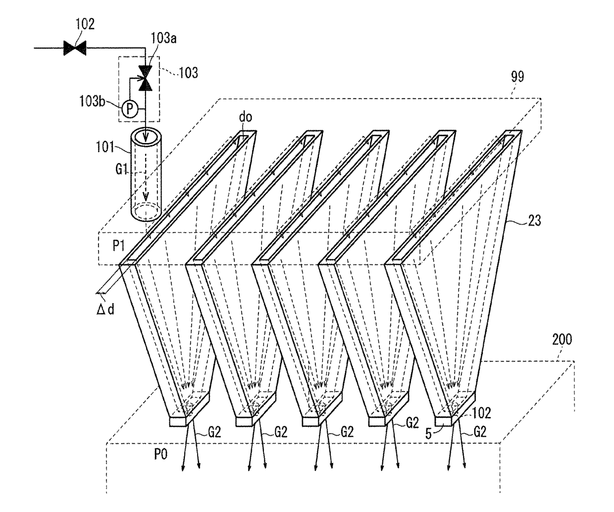
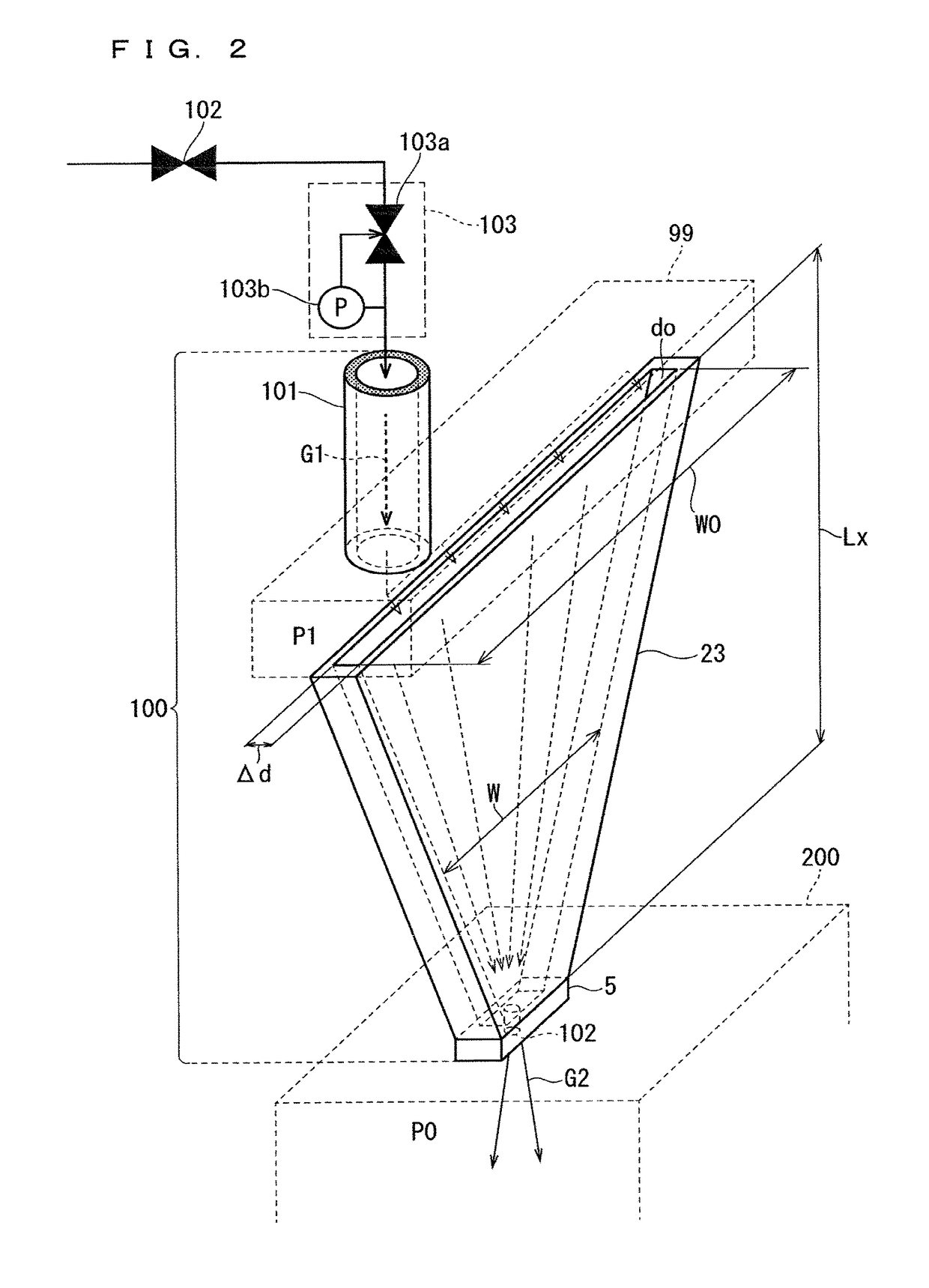
[0045]FIG. 2 is a perspective view schematically illustrating a configuration of a remote plasma type film formation treatment system configured to include a gas jetting apparatus 100 for jetting non-heated, heated, and discharge gases into a film formation apparatus (hereinafter simply referred to as a gas jetting apparatus) and a treatment chamber 200, according to this exemplary embodiment.

[0046]The non-heated, gas jetting apparatus 100 and the treatment chamber 200 are partitioned by a flange. That is, the flange is a member for joining the gas jetting apparatus 100 and the treatment chamber 200, where a main surface of the flange configures a bottom surface of the gas jetting apparatus 100, while another main surface of the flange configures a top surface of the treatment chamber 200. In here, the gas jetting apparatus 100 and the treatment chamber 200 are internally coupled each other via a jetting-out hole 102.

[0047]As shown in FIG. 2, the gas jetting apparatus 100 is configu...

second exemplary embodiment

[0082]In this exemplary embodiment, in a gas jetting cell unit 23, by heating a gas G1, the gas G1 is served as a radical gas. The gas jetting cell unit 23 according to this exemplary embodiment jets the radical gas G2. FIG. 4 is a view illustrating a configuration of a gas jetting apparatus 100 for jetting a heated gas, according to this exemplary embodiment.

[0083]A gas species to be heated to generate a radical gas G2 may be an ozone gas (i.e. in FIG. 4, a gas G1 supplied from the gas supply unit 101 to the gas jetting apparatus 100 is an ozone gas).

[0084]Generally, in an ozone generator, dielectric barrier discharge is used to generate an ozone gas. Recently, a technology for forming an oxide film using an ozone gas by supplying a high density ozonized gas, without including a nitrogen gas, in an amount of approximately 400 g / m3 to a CVD apparatus has already been established.

[0085]With such a film formation technology, for example, a reduced pressure atmosphere and a heated atmo...

third exemplary embodiment

[0098]In a gas jetting apparatus 100 according to this exemplary embodiment, in a gas gap do of a gas jetting cell unit 23, dielectric barrier discharge is generated, and the dielectric barrier discharge is used to generate a high quality radical gas. The gas jetting cell unit 23 according to this exemplary embodiment jets out the radical gas in a beam shape having directivity at a higher velocity. FIG. 5 is a view illustrating a configuration of the gas jetting apparatus 100 according to this exemplary embodiment.

[0099]The gas jetting apparatus 100 described in the first exemplary embodiment and the gas jetting apparatus 100 according to this exemplary embodiment have identical configurations excluding that members described below are added.

[0100]Applying a higher AC voltage onto an electrode surface to generate dielectric barrier discharge, and then, utilizing the dielectric barrier discharge to allow a gas to dissociate to generate a radical gas is widely known. The gas jetting a...


PUM

PropertyMeasurementUnit
gas pressureaaaaaaaaaa
diameteraaaaaaaaaa
gas pressure P1aaaaaaaaaa

Abstract

The present invention provides a gas jetting apparatus for a film formation apparatus. The gas jetting apparatus is capable of uniformly jetting, even onto a treatment-target object having a high-aspect-ratio groove, a gas into the groove. The gas jetting apparatus (100) according to the present invention includes a gas jetting cell unit (23) for rectifying a gas and jetting the rectified gas into the film formation apparatus (200). The gas jetting cell unit (23) has a fan shape internally formed with a gap (d0) serving as a gas route. A gas in a gas dispersion supply unit (99) enters from a wider-width side of the fan shape into the gap (d0), and, due to the fan shape, the gas is rectified, accelerated, and output from a narrower-width side of the fan shape into the film formation apparatus (200).

Description

TECHNICAL FIELD[0001]The present invention relates to a gas jetting apparatus for a film formation apparatus, and is applicable, for example, a gas jetting apparatus capable of jetting out at a higher velocity having directivity various gases useful for treatment of a treatment-target object placed under a reduced pressure atmosphere in a treatment chamber.BACKGROUND ART[0002]In various application fields including a semiconductor manufacturing field, multi-function, high quality thin films (for example, high insulation thin films, semiconductor thin films, high dielectric thin films, light-emitting thin films, high magnetic thin films, and super-hard thin films) have been demanded.[0003]For example, in scenes of manufacturing semiconductor apparatuses, semiconductor chips are formed with, for example, a high conductive film having a lower impedance so as to correspond to circuit wiring, a high magnetic film having a circuit wiring and coil function and a magnetic function, a high d...

Claims


Application Information

Patent Timeline
Patent Type & Authority Applications(United States)
IPC IPC(8): C23C16/455C23C16/503
CPCC23C16/45561C23C16/45559C23C16/503B01J4/00C23C16/455H01L21/31C23C16/045C23C16/452C23C16/4551C23C16/45563C23C16/4557C23C16/45572C23C16/45582C23C16/513H01L21/205C23C16/45557C23C16/448C23C16/4488H01L21/02263
Inventor TABATA, YOICHIROWATANABE, KENSUKENISHIMURA, SHINICHI
Owner TOSHIBA MITSUBISHI-ELECTRIC IND SYST CORP
Why Eureka
Try Eureka