Autonomous Navigation using Visual Odometry

a technology of visual odometry and autonomous navigation, applied in the field of visual odometry, can solve the problems of increasing the cost of robots, difficult to find a corresponding point viewed by one camera, and unaffordable household applications, and achieve the effect of reducing the cost of autonomous navigation

Inactive Publication Date: 2017-09-28
SHARP KK
View PDF0 Cites 115 Cited by
  • Summary
  • Abstract
  • Description
  • Claims
  • Application Information

AI Technical Summary

Benefits of technology

[0031]Unlike conventional systems, the navigation system is enabled with only a stereo camera as a sensor. Compared to conventional robot navigation syste

Problems solved by technology

With multiple cameras it can be difficult to find a corresponding point viewed by one camera in the image of th

Method used


Image

  • Autonomous Navigation using Visual Odometry
  • Autonomous Navigation using Visual Odometry
  • Autonomous Navigation using Visual Odometry

Examples


Embodiment Construction

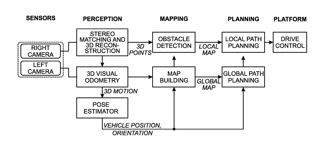
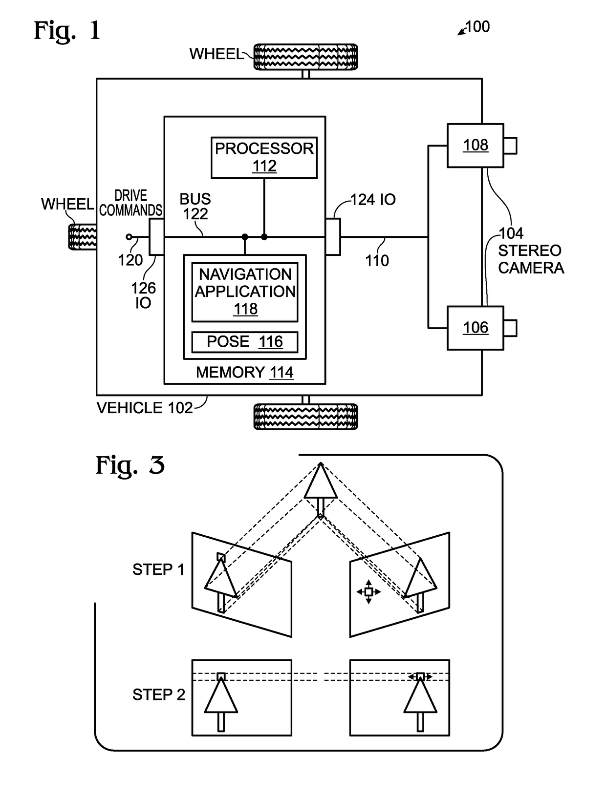
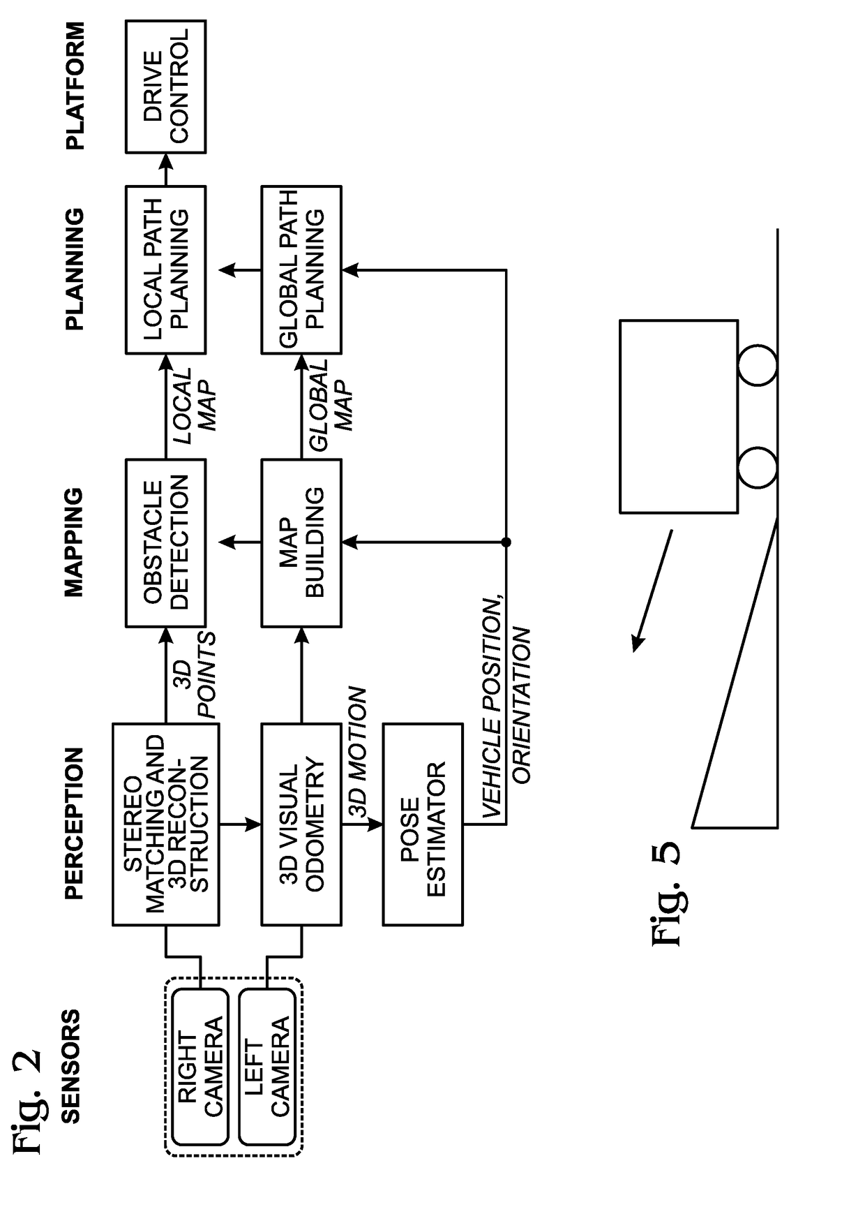
[0046]FIG. 1 is a schematic block diagram of a system for autonomously navigating a vehicle. The system 100 comprises a vehicle (robot) 102. A stereo camera 104, with a right camera 106 and a left camera 108, is mounted on the vehicle 102 and has an output on line 110 to supply image pairs. Each image pair includes a right image and a left image. The system 100 further comprises a processor 112 and a non-transitory memory 114. Residing in memory 114 is a stored vehicle pose 116, where a vehicle pose is defined herein as a position and orientation with respect to a coordinate frame. As described in more detail below, the coordinate frame may exist in a camera or world coordinate systems for example. A navigation application 118 is embedded in the non-transitory memory 114 and includes a sequence of processor executable instructions to perform the following functions. The navigation application 118 detects a plurality of matching feature points in a first matching image pair, and dete...


PUM


Abstract

A system and method are provided for autonomously navigating a vehicle. The method captures a sequence of image pairs using a stereo camera. A navigation application stores a vehicle pose (history of vehicle position). The application detects a plurality of matching feature points in a first matching image pair, and determines a plurality of corresponding object points in three-dimensional (3D) space from the first image pair. A plurality of feature points are tracked from the first image pair to a second image pair, and the plurality of corresponding object points in 3D space are determined from the second image pair. From this, a vehicle pose transformation is calculated using the object points from the first and second image pairs. The rotation angle and translation are determined from the vehicle pose transformation. If the rotation angle or translation exceed a minimum threshold, the stored vehicle pose is updated.

Description

BACKGROUND OF THE INVENTION[0001]1. Field of the Invention[0002]This invention generally relates to visual odometry and, more particularly, to a system and method for using visual odometry to autonomously navigate a vehicle.[0003]2. Description of the Related Art[0004]In navigation, odometry is the use of data from the movement of actuators to estimate change in position over time through devices such as rotary encoders to measure wheel rotations. Visual odometry is the process of determining equivalent odometry information using sequential camera images to estimate the distance traveled. Many existing approaches to visual odometry are based on the following stages:[0005]1) Acquire input images: using either single, stereo, or omnidirectional cameras.[0006]2) Image correction: apply image processing techniques for lens distortion removal, etc.[0007]3) Feature detection: define interest operators, and match features across frames and construct optical flow field.[0008]4) Use correlat...

Claims


Application Information

Patent Timeline
IPC IPC(8): G05D1/02H04L12/40G06K9/00G06T7/20G06T7/00
CPCG05D1/0251G06T7/20G06T7/0075G06K9/00805G05D2201/0213G06T7/002G06T2207/20228H04L2012/40273G06T2207/30261H04L12/40H04L12/40013G05D1/0253G06T7/246G06T7/593G06V20/58G06V10/757G06T7/55
Inventor LIAO, MIAOLI, MINGHONG, SOONHAC
Owner SHARP KK
Why Eureka
Try Eureka