Eureka AIR delivers breakthrough ideas for toughest innovation challenges, trusted by R&D personnel around the world.

Driving control mechanism and driving control device

Active Publication Date: 2017-10-05
SUBARU CORP
View PDF6 Cites 5 Cited by
  • Summary
  • Abstract
  • Description
  • Claims
  • Application Information

AI Technical Summary

Benefits of technology

The invention is about a transmission system for internal combustion engines that can adjust the gear ratio to optimize performance under different driving conditions. The transmission can decrease the gear ratio to a speed where the engine stops or increase the gear ratio to maximize the engine's power output. This allows for smooth and efficient shifting during gear changes and can provide better overall performance. The invention also includes a method for reducing the impact and noise caused by gear changes, which improves the overall quality of the vehicle.

Problems solved by technology

However, the invention disclosed by JP-A No. 2015-150916 has a problem that a driving force transmitted to the driving wheel is reduced due to control on a transmission gear ratio of a transmission.

Method used


Image

  • Driving control mechanism and driving control device
  • Driving control mechanism and driving control device
  • Driving control mechanism and driving control device

Examples


Embodiment Construction

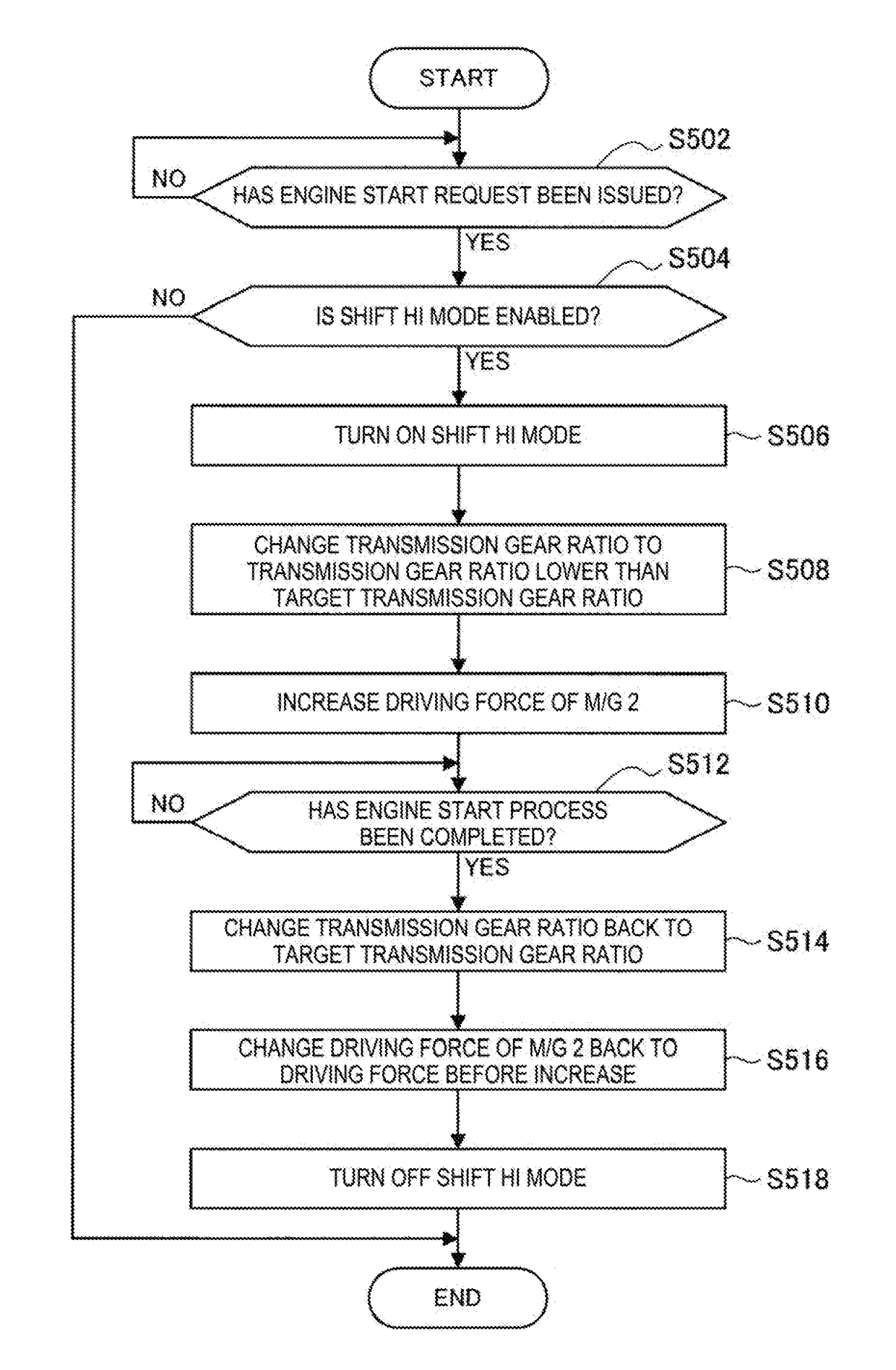
[0024]Hereinafter, preferred implementations of the present invention will be described in detail with reference to the appended drawings. Note that, in this specification and the appended drawings, structural elements that have substantially the same function and structure are denoted with the same reference numerals, and repeated description of these structural elements is omitted.

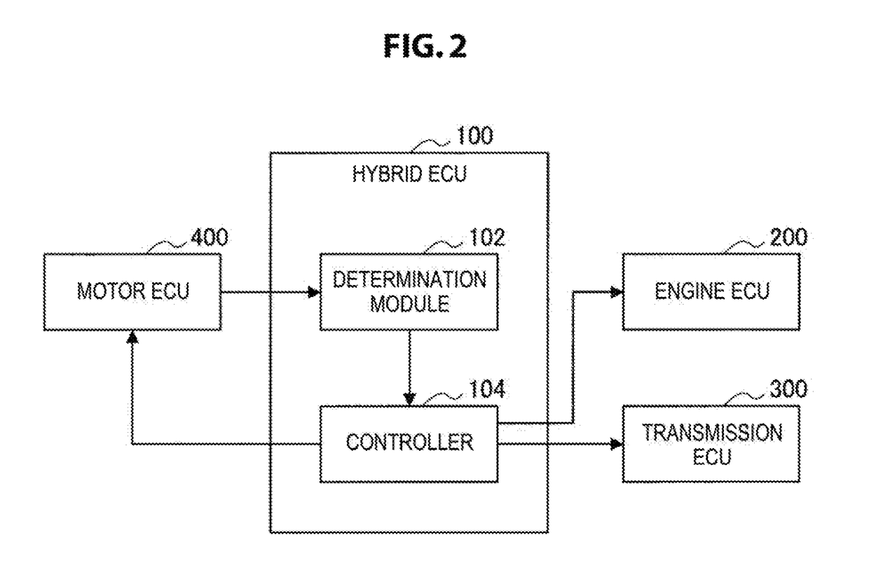
[0025]A driving control mechanism according to an implementation of the present invention will be described.

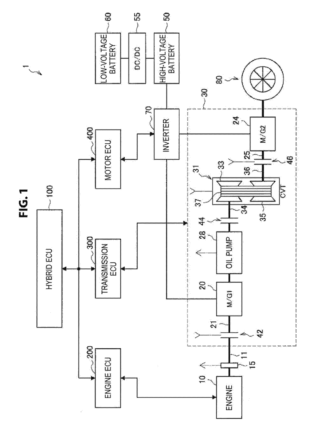
[0026]With reference to FIG. 1, an entire configuration of a driving control mechanism 1 will be described. FIG. 1 is a diagram illustrating an example of the entire configuration of the driving control mechanism 1 according to an implementation of the present invention.

[0027]FIG. 1 illustrates the driving control mechanism 1 of a hybrid vehicle. The driving control mechanism 1 includes an engine 10, a first motor generator 20, and a second motor generator 24, and is a power unit capable of using t...


PUM


Abstract

A driving control mechanism includes: a motor that is coupled to a driving wheel; a transmission that is coupled to the driving wheel; and an internal combustion engine that is coupled to an input shaft of the transmission. In a first state in which a driving force of the motor is transmitted to the driving wheel and a driving force of the internal combustion engine is not transmitted to the driving wheel, the transmission reduces a transmission gear ratio to a value less than a target transmission gear ratio according to a requested driving force when a transition request to a second state in which driving forces of the motor and the internal combustion engine are transmitted to the driving wheel is issued. The motor increases a driving force to be transmitted to the driving wheel when the transition request is issued.

Description

CROSS-REFERENCE TO RELATED APPLICATIONS[0001]The present application claims priority from Japanese Patent Application No. 2016-066473 filed on Mar. 29, 2016, the entire contents of which are hereby incorporated by reference.BACKGROUND1. Technical Field[0002]The present invention relates to driving control mechanisms and driving control devices.2. Related Art[0003]In recent years, hybrid technologies in vehicle power have been researched and developed. The hybrid technologies include a technology in which an engine and motors are used as power sources. In general, a vehicle using such a hybrid technology travels in an electric vehicle (EV) mode or a hybrid electric vehicle (HEV) mode. In the EV mode, a vehicle is driven by motors. In the HEV mode, a vehicle is driven by motors or an engine.[0004]Sometimes a shock occurs in a vehicle when the mode is switched from the EV mode to the HEV mode. For example, shock occurrence possibility when engaging a driving wheel side and an engine si...

Claims


Application Information

Patent Timeline
IPC IPC(8): B60W20/15B60K6/48B60W30/20B60W10/08B60W10/107B60L50/16
CPCB60W20/15B60W10/08B60W10/107B60W30/20B60K6/48Y10S903/945B60W2510/244B60W2710/083B60W2710/1005B60Y2200/92Y10S903/93B60W2510/083B60W10/06B60W10/10B60W20/00B60W30/182B60W20/30B60W20/40Y02T10/62Y02T10/72
Inventor SUZUKI, HIROYUKIINOUE, WATARU
Owner SUBARU CORP
Why Eureka
Eureka Blog
Learn More