Monitoring device

a technology of monitoring device and load cell, which is applied in the direction of measuring device, heat measurement, instruments, etc., can solve the problems of reducing the operation rate, increasing the workload of inspection, and difficult wiring of attaching load cells to shafts, so as to increase the amount of heat flowing from the bearing to the housing

Active Publication Date: 2017-10-12
DENSO CORP
View PDF0 Cites 17 Cited by
  • Summary
  • Abstract
  • Description
  • Claims
  • Application Information

AI Technical Summary

Benefits of technology

[0013]In the monitored device, when the shaft rotates, the frictional heat of an inner ring, an outer ring, and rolling elements in the bearing heats the entire periphery of the bearing. As a result, heat flows from the entire periphery of the bearing to the housing. This heat flux becomes temperature drifts in the outputs of the heat flux sensors. Additionally, in the monitored device, when a load is applied to the shaft in its radial direction while the shaft is rotating, the thermal dose increases at a part of the bearing in the direction in which the load is applied to the shaft. As a result, the amount of heat flowing from the part of the bearing to the housing increases. In the monitoring device, this heat flow causes the output of a part of the heat flux sensors to increase. Thus, the detector removes temperature drifts from the outputs of the heat flux sensors, based on an output corresponding to the difference between the thermal electromotive forces of the heat flux sensors positioned apart from each other in the circumferential direction of the bearing. This allows the detector to extract an output signal corresponding to the load applied to the shaft or bearing in a radial direction thereof. Accordingly, the monitoring device disclosed herein can monitor a load applied to the shaft or bearing in a radial direction thereof while the shaft of the target device is rotating.

Problems solved by technology

However, the appearance inspection may increase the workload for inspection and reduce the rate of operation due to stopping of the forming machine when a defective product has been found.
However, attaching load cells to the shafts is difficult in terms of wiring since they rotate when the forming machine is in operation.
Thus, even if load cells are attached to the bearings, detecting the loads applied to the shafts or bearings is difficult.
The above-described problems concerning monitoring devices are not limited to arise in forming machines but equally apply to various devices (devices to be monitored) including a shaft and bearing.

Method used


Image

  • Monitoring device
  • Monitoring device
  • Monitoring device

Examples


first embodiment

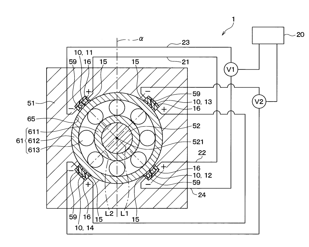
[0030]A first embodiment of a monitoring device will be described. As shown in FIGS. 1 to 3, a monitoring device 1 of this embodiment is attached to a forming machine 50 which is the device to be monitored. The monitoring device 1 monitors a load applied to a shaft or bearing in the forming machine 50.

[0031]First, the forming machine 50 will be described.

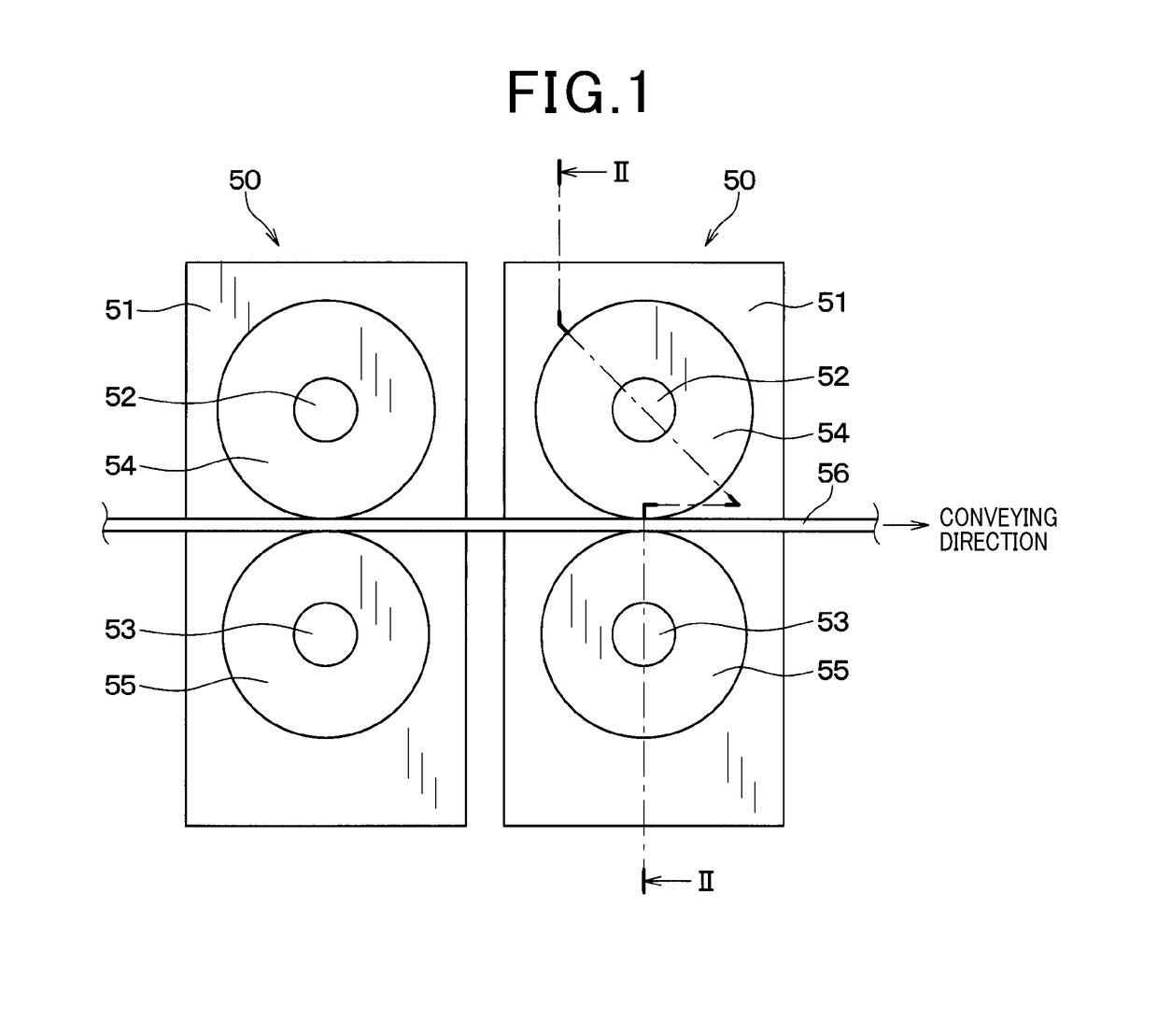
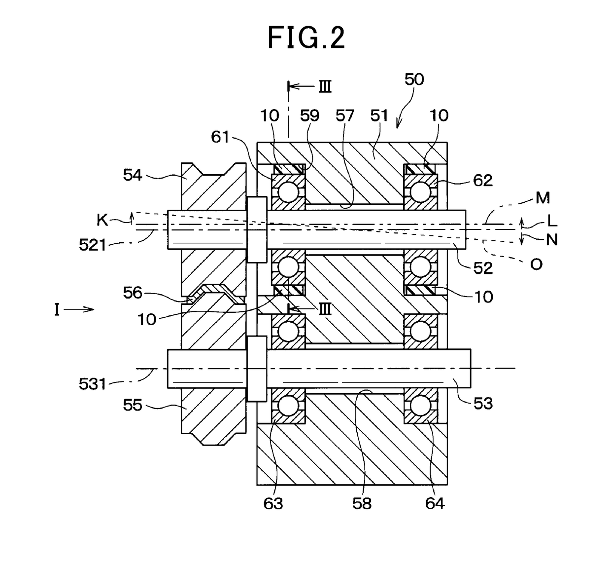
[0032]As shown in FIGS. 1 and 2, the forming machine 50 includes a housing 51, two shafts 52, 53, and two forming rollers 54, 55. The two shafts 52, 53 are provided in the housing 51 such that they can rotate about their axes. Each forming roller 54, 55 is fixed to the corresponding shaft 52, 53 at an end thereof. The shaft 52 and forming roller 54 in FIG. 1 will be hereinafter referred to as a first shaft 52 and first forming roller 54. Additionally, the shaft 53 and forming roller 55 in FIG. 1 will be referred to as a second shaft 53 and second forming roller 55.

[0033]The forming machine 50 passes a strip material serving as a pro...

second embodiment

[0088]The monitoring device 1 of a second embodiment differs from the first embodiment in the method of detecting an abnormality, performed by the detector 20.

[0089]FIG. 8 shows examples of the changes in the first signal V1 and second signal V2 over time when the forming machine 50 is in operation. The horizontal axis in FIG. 8 shows the time that has elapsed since the forming machine 50 started operation. The vertical axis shows voltage.

[0090]In FIG. 8, the solid line P shows the change in the first signal V1. The dashed line Q shows the change in the second signal V2. Here, it is assumed that the first signal V1 becomes a positive voltage signal when the load at one of the ends of the line L1 connecting the first heat flux sensor 11 and second heat flux sensor 12 increases. The first signal V1 becomes a negative voltage signal when the load at the other end of the line L1 connecting the first heat flux sensor 11 and second heat flux sensor 12 increases.

[0091]It is assumed that th...

third embodiment

[0096]The monitoring device 1 of the third embodiment differs from the first embodiment in the way the first to fourth heat flux sensors 11 to 14 are attached to the bearing.

[0097]As shown in FIG. 9, the housing 51 in the forming machine 50 includes threaded holes 66 extending outwards in radial directions of the first bearing 61 (radially outwards) from the inner walls of the recesses 59. Screw members 30 are inserted into the threaded holes 66. Each screw member 30 is engaged with the internal thread formed on the inner wall of the corresponding threaded hole 66. The leading ends of the screw members 30 on the bearing side are in contact with the first to fourth heat flux sensors 11 to 14. The screw members 30 press the heat flux sensors 10 against the outer wall of the first bearing 61. Accordingly, the third embodiment prevents gaps being formed between the outer wall of the first bearing 61 and the heat flux sensors 10.

[0098]The screw members 30 are formed of a material with a ...


PUM

PropertyMeasurementUnit
heat fluxesaaaaaaaaaa
thermal electromotive forceaaaaaaaaaa
thermal conductiveaaaaaaaaaa

Abstract

A monitoring device monitors a forming machine (target device). The forming machine includes a housing, a bearing attached to the housing, and a shaft placed radially inside the bearing. The monitoring device includes a plurality of heat flux sensors and a detector. The heat flux sensors are provided on the radially outer side of the bearing and spaced from each other in the circumferential direction of the bearing. The heat flux sensors output a signal corresponding to heat fluxes through faces thereof on the bearing side and faces thereof on the other side. The detector detects a load applied radially to the shaft or bearing, based on the output from the heat flux sensors.

Description

CROSS-REFERENCE TO RELATED APPLICATION[0001]This application is based on and claims the benefit of priority from earlier Japanese Patent Application No. 2016-78340 filed Apr. 8, 2016, the description of which is incorporated herein by reference.BACKGROUND OF THE INVENTIONTechnical Field of the Invention[0002]The present disclosure concerns a technique for monitoring a load applied to a shaft or bearing in a target device.Description of the Related Art[0003]For example, JP 5376086 B discloses a heat flux sensor for detecting heat flux.[0004]A forming machine as follows is known. The forming machine passes a strip material serving as a processing target between two forming rollers. The forming machine applies loads to the processing target with the two forming rollers to process the processing target continuously. Such forming machine is desired to meet the following requirements in order to form the processing target into a desired shape. Specifically, the requirements are that the l...

Claims


Application Information

Patent Timeline
Patent Type & Authority Applications(United States)
IPC IPC(8): B21B38/00G01K17/00
CPCB21B38/006B21B2038/002G01K17/00B21C51/00B21D5/08G01K13/08G01K17/20
Inventor GOUKO, NORIOTANIGUCHI, TOSHIHISASAKAIDA, ATUSIOKAMOTO, KEIJISHIRAISHI, YOSHIHIKOASANO, MASAHIRO
Owner DENSO CORP
Why Eureka
Try Eureka