Composite hydrological monitoring system

a hydrological monitoring and composite technology, applied in the field of composite hydrological monitoring systems, can solve the problems of complex circuit structure, high cost, complex structure and economic disadvantages, etc., and achieve the effects of low cost, simple structure and easy construction

Active Publication Date: 2017-10-12
NAT APPLIED RES LAB
View PDF0 Cites 20 Cited by
  • Summary
  • Abstract
  • Description
  • Claims
  • Application Information

AI Technical Summary

Benefits of technology

[0006]It is one object of the present invention to provide a composite hydrological monitoring system for monitoring scour depth, water level, flow velocity, or the like. The composite hydrological monito...

Problems solved by technology

However, the precision of the manual inspection rely on the experience of the inspectors, and the inspection operated on water also threatens the lives of the inspectors.
However, it still has the...

Method used


Image

  • Composite hydrological monitoring system
  • Composite hydrological monitoring system
  • Composite hydrological monitoring system

Examples


first embodiment

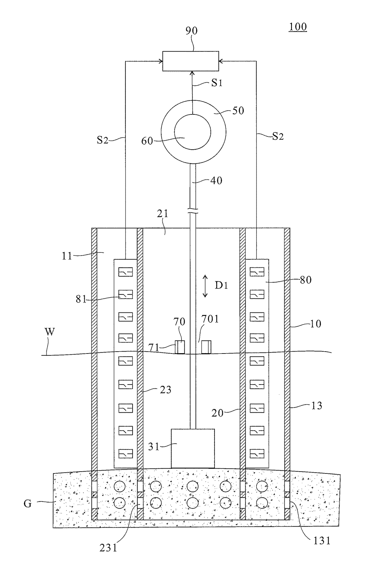
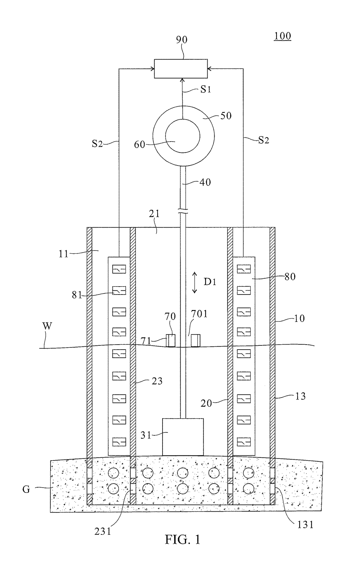
[0036]Please refer to FIG. 4 for detail description between the float 70 and the second sensor 81. As illustrated in FIG. 4, the sensing elements 81 of the second sensor 80 are disposed symmetrically on the opposite inner sidewall of the first hollow base body (not shown) and the opposite outer sidewall of the second hollow base body (not shown) for forming a first sensing part 801 and a second sensing part 803. In this case, the magnetic switch is used as the sensing element 81 for exemplifying the Those sensing element 81 of the first sensing part 801 and the second sensing part 803 located at positions Y1, Y2, Y3 . . . are connected in parallel to two wires 83 and are arranged in a row along the vertical direction at a predetermined interval of 5 cm from one another. Accordingly, as illustrated in FIG. 4, when the float 70 is floating on the water surface that corresponds to the sensing element 81 at the vertical position Y3, the magnetic element 71 on the float 70 triggers the ...

second embodiment

[0040]In addition, another embodiment of the second sensor 80 is illustrated in FIG. 7. As illustrated in FIG. 7, the induced coil surrounds the positions Y1, Y2, Y3 . . . of the outer sidewall of the second hollow base body 20 as the sensing elements 81. When the float 70 passes vertically through the corresponding inductive coil along with the water surface, the magnetic element 71 having high magnetic permeability on the float 70 will affect the inductive coil and cause the electric or magnetic changes (such as inductance, electromotive force, magnetic force, or the like). Accordingly, the location of the float 70 may be determined by detecting the electric or magnetic changes of the inductive coil (such as inductance, electromotive force, magnetic force, or the like) when the float 70 passes through the inductive coil. Similarly, the vibration of the float 70 caused by the turbulence may result in electric or / and magnetic changes so that the flow velocity of the river may be obt...


PUM


Abstract

Disclosed is a composite hydrological monitoring system, in which a counterweight component and a test component are respectively connected to both opposite ends of a strip and a plurality of sensors are disposed at different vertical positions. Accordingly, the scour depth can be measured by sensing the location of the counterweight component, whereas the water level and/or flow velocity can be determined by signals from the sensors. When the counterweight component moves downward with sinking of the riverbed, the strip would be pulled down and thus causes the test component to present a change in mechanical energy. Accordingly, the sinking depth can be measured by sensing the change of the mechanical energy. Additionally, since the water level variation would cause signal changes of the sensors arranged in a row along a vertical direction, the change of water level can be determined accordingly.

Description

CROSS REFERENCE TO RELATED APPLICATION[0001]This application claims the benefits of the Taiwan Patent Application Serial Number 105111172, filed on Apr. 11, 2016, the subject matter of which is incorporated herein by reference.BACKGROUND OF THE INVENTION1. Field of the Invention[0002]The present invention relates to a composite hydrological monitoring system. More specifically, the present invention relates to a composite hydrological monitoring system that measures the scour depth and the water level and / or the flow velocity.2. Description of Related Art[0003]The conventional method for detecting the scour depth and the water level is operated by manual inspection. However, the precision of the manual inspection rely on the experience of the inspectors, and the inspection operated on water also threatens the lives of the inspectors.[0004]In recent years, many techniques for monitoring the scouring condition and water level have been developed. For example, the time-domain reflectio...

Claims


Application Information

Patent Timeline
IPC IPC(8): G01C13/00G01F23/30G01F1/05
CPCG01C13/008G01F23/30G01F1/05G01D21/02E02B3/00G01F23/64G01F1/005G01F23/0007G01F23/0023G08B21/182G08B25/08G01F23/80G08B21/00
Inventor LIN, YUNG-BINCHEN, YU-CHIEHLIAO, TAI-SHANCHANG, KUO-CHUNLEE, BO-HANWANG, YUNG-KANGGU, MENG-HUANG
Owner NAT APPLIED RES LAB
Why Eureka
Try Eureka