License plate radio electronic identifier

a radio electronic and license plate technology, applied in the field of license plate radio electronic identification, can solve the problems of complicated process, electronic tags mounted in the slot may not be able to disengage from the slot, and abnormal signals, and achieve the effects of good reading sensitivity, long distance reading, and cost-effectiveness

Active Publication Date: 2017-10-12
RFID INTEGRATED MARKETING CO LTD
View PDF0 Cites 8 Cited by
  • Summary
  • Abstract
  • Description
  • Claims
  • Application Information

AI Technical Summary

Benefits of technology

[0004]Preferably, the RFID tag is mounted in the elongate recess. The elongate recess is filled with an insulating sealant. Through the insulating sealant, the RFID tag is restricted within the elongate recess, thereby attaining a positioning effect.
[0005]Preferably, the slot of the metal film antenna on the RFID tag is a rectangular slot matching the license plate, and the groove is perpendicular to the slot. The inducting frequency band and the field pattern of the electromagnetic wave signal reflected by the license plate can be adjusted through the shape and size of the slot and the width of the groove, so that the RFID tag can achieve the effects of good reading sensitivity and long distance reading in the working frequency band.
[0006]Preferably, upper and lower portions of the plate body of the plate holder of the identifier each have the pair of perforations corresponding to the pair of the mounting holes of the license plate. When the user wants to mount the identifier in cooperation with the license plate to the vehicle, the license plate is located at its original position of the vehicle. The license plate may be inserted in the plate receiving groove at the lower end of the identifier, or the license plate may be inserted in the plate receiving groove at the upper end of the identifier. The elongate frame of the identifier is transversely arranged at the lower end edge or the upper end edge of the license plate to maintain a good matching isolated space relative to the metal film antenna of the RFID tag in the elongate recess. When the license plate is mounted on the vehicle, the RFID tag transversely disposed on the surface of the upper edge or the lower edge of the license plate is resistant to a metal interference and capable of long distance reading.

Problems solved by technology

This may lead to an abnormal signal.
Although the problem that the metallic surface of the license plate affects the antenna of the electronic tag has been improved and the performances of long distance reading and transmitting signals can be achieved, it still has the problem that the electronic tag mounted in the slot may disengage from the slot.
In particular, mounting an electronic license plate is not a policy of the traffic policy.
Although this way neither modify the license plate and nor transgress against the low, it is a complicated process for the metal plate integrally formed with the antenna to be formed with the slot.
Besides, after the electronic tag is placed in the slot, the slot is filled with glue for positioning the electronic tag, and the surface of the glue needs polishing and coating (or painting) and other surface treatment process, resulting in low production capacity (low production efficiency) and high manufacturing costs.
Sometimes, due to economic considerations, it affects the popularity of mounting RFID tags to vehicles.

Method used


Image

  • License plate radio electronic identifier
  • License plate radio electronic identifier
  • License plate radio electronic identifier

Examples


Embodiment Construction

[0023]Embodiments of the present invention will now be described, by way of example only, with reference to the accompanying drawings.

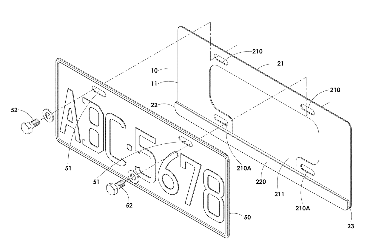
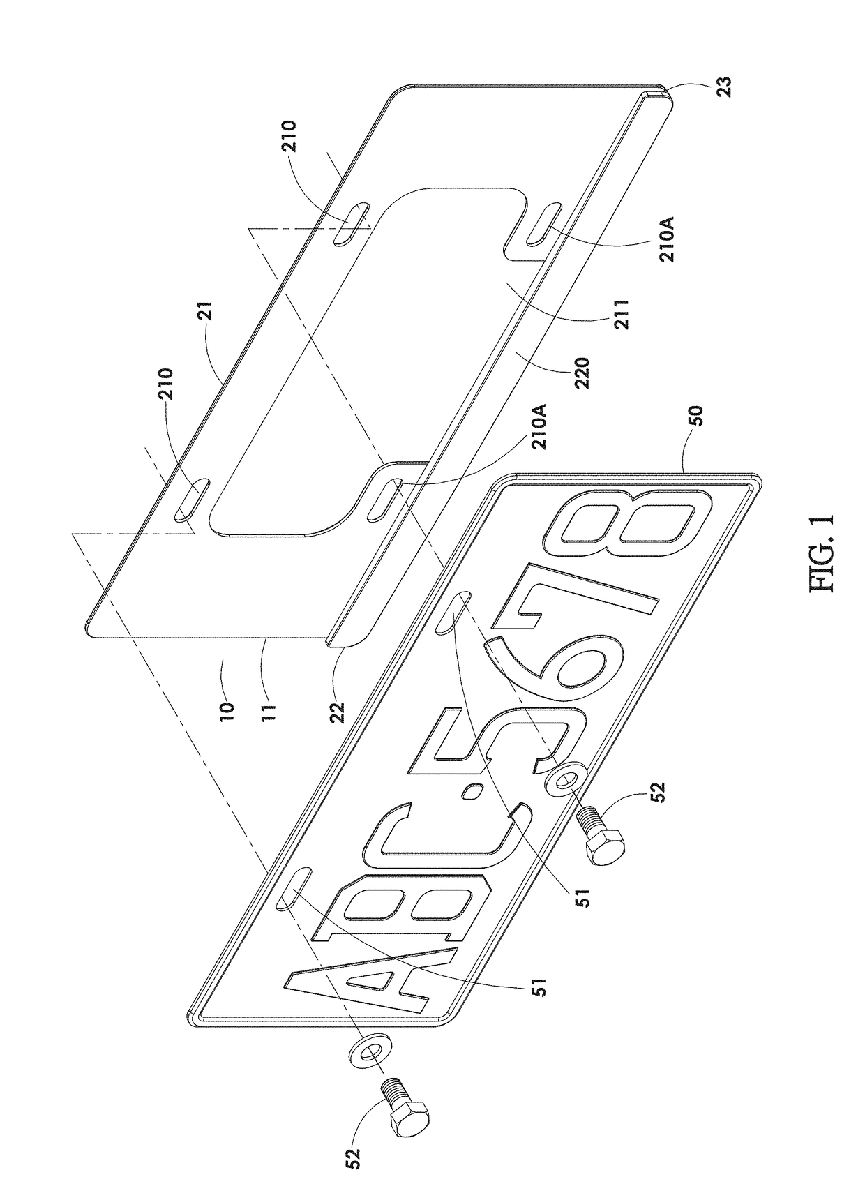
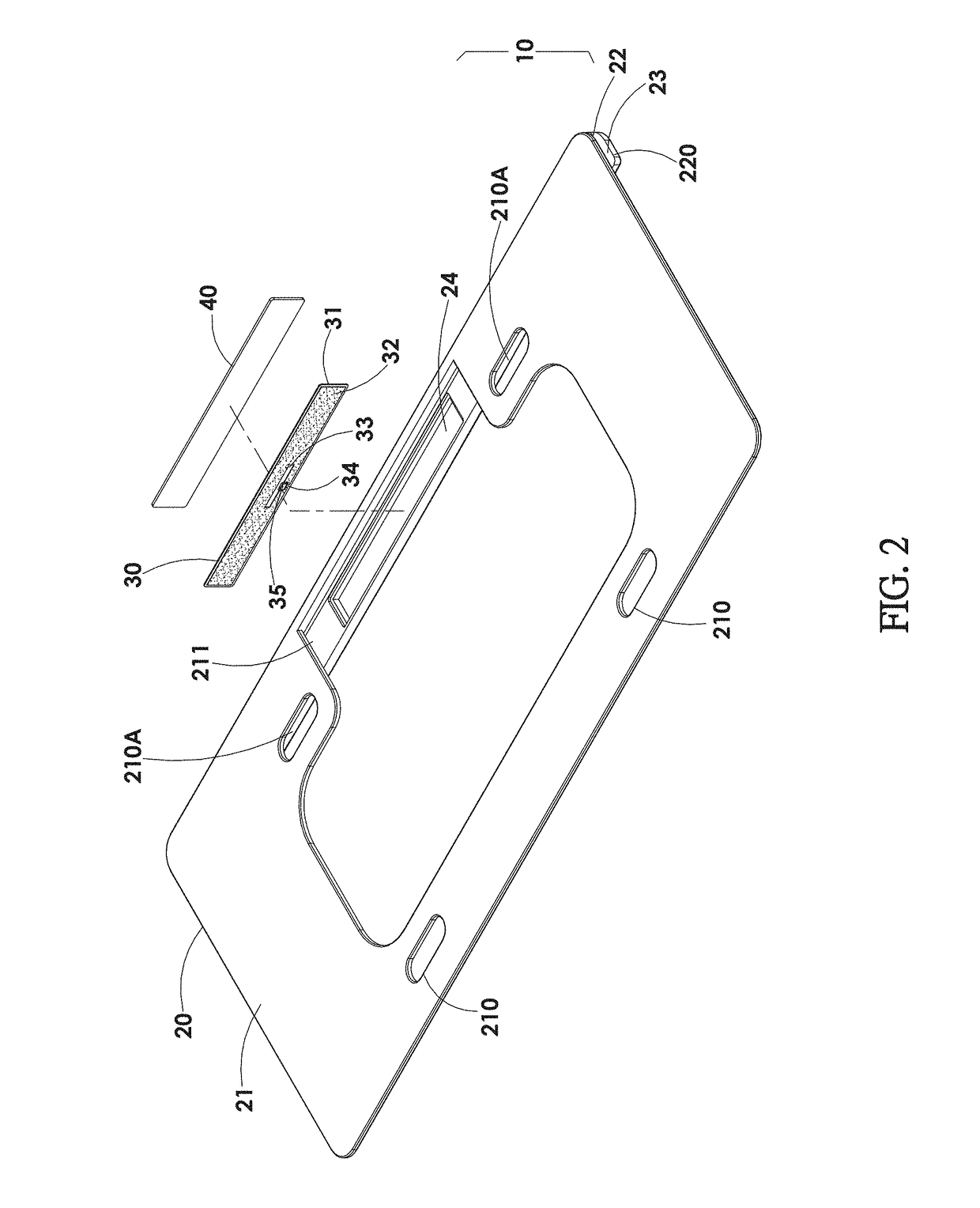
[0024]A license plate radio electronic identifier, as shown in FIG. 1 to FIG. 6, comprises an identifier 10 matching a license plate 50 installed to a vehicle (not shown) for radio frequency identification by using a radio frequency reader (not shown). The identifier 10 comprises a plate holder 20, an RFID (radio frequency identification) tag 30, and a sealing sheet 40.

[0025]The plate holder 20 is made of an insulating polymeric (plastic) material by injection molding, and has a plate body 21. The plate body 21 has a pair of perforations 210 corresponding to a pair of mounting holes 51 of the license plate 50. One side of the plate body 21 is formed with a tag setting frame portion 22 having an L-shaped cross section. The tag setting frame portion 22 has an elongate frame 220. A plate receiving groove 23 is formed between the elongate frame 220 and th...


PUM


Abstract

A license plate radio electronic identifier is provided. Through an isolated space defined between an RFID tag in an elongate frame of an identifier and a license plate to form a resonant cavity at a slot of a metal film antenna on the RFID tag, the metal film antenna can resonate and sense an electromagnetic wave signal reflected by the surface of the license plate through the resonant cavity. The electromagnetic wave signal of a frequency band is transmitted to a radio frequency identification chip under the action of the frequency band and the field pattern adjustment of the slot and a groove. The overall structure of the identifier serves as radio identification for a vehicle. The identifier is resistant to a metal interference and capable of long distance reading and can be put into mass production and is cost-effective.

Description

FIELD OF THE INVENTION[0001]The present invention relates to an identifier, and more particularly to a license plate radio electronic identifier that is resistant to a metal interference and capable of long distance reading and can be put into mass production and is cost-effective.BACKGROUND OF THE INVENTION[0002]Radio Frequency Identification (RFID) is widely used in many fields, such as industrial automation, commercial automation, and transportation control management, and so on. In general, a microstrip antenna itself has the shortcoming of a narrow frequency to cause many restrictions on an antenna design. Most are designed into a single frequency and a narrow frequency. UHF electronic tags often use printed antennas. The majority are microstrip antennas and printed dipoles. If a UHF electronic tag is applied to a license plate, the metallic surface of the license plate makes the signal reflected easily. This may lead to an abnormal signal. Sometimes, the RFID tag cannot be act...

Claims


Application Information

Patent Timeline
Patent Type & Authority Applications(United States)
IPC IPC(8): G06K19/077
CPCG08G1/017G06K19/07758
Inventor PAI, DANIEL
Owner RFID INTEGRATED MARKETING CO LTD
Why Eureka
Try Eureka