Post acquisition calibration

a technology of tomographic imaging and calibration, applied in the field of post acquisition calibration, can solve the problems of poor image quality and inability to correct poor image quality, and achieve the effect of improving radiographic image quality, improving accuracy and quality of reconstructed volum

Inactive Publication Date: 2017-10-19
CARESTREAM HEALTH INC
View PDF10 Cites 4 Cited by
  • Summary
  • Abstract
  • Description
  • Claims
  • Application Information

AI Technical Summary

Benefits of technology

[0009]A method of operating a tomographic imaging system is disclosed. A number of radiographic images of an object are captured at a first orientation of the imaging system's source and detector. After the radiographic images are captured and stored, geometric calibration data for the system is generated (e.g., measured), corresponding to the first orientation of the system. A three dimensional image of the object is reconstructed using the measured geometric calibration data corresponding to the first orientation. An advantage

Problems solved by technology

Although 3-D images of diagnostic quality can be generated using CBCT systems and technology, a number of technical challenges remain.
In some cases, for example, the ability to correct poor image quality may be lacking as a result of not having geometric calibration data for a particular orientation of the gantry assembly used in

Method used


Image

  • Post acquisition calibration
  • Post acquisition calibration
  • Post acquisition calibration

Examples


Embodiment Construction

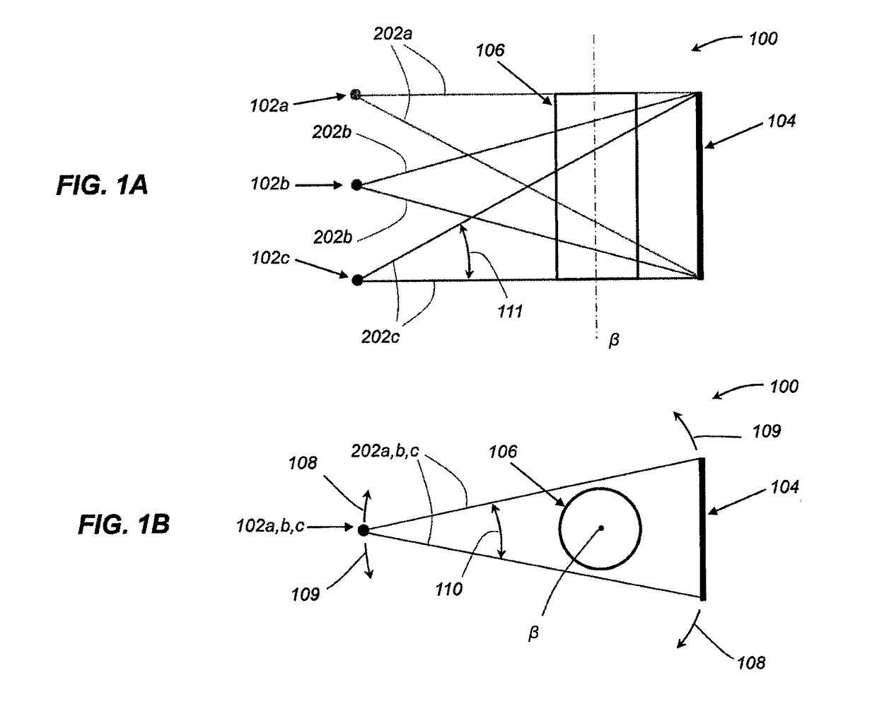
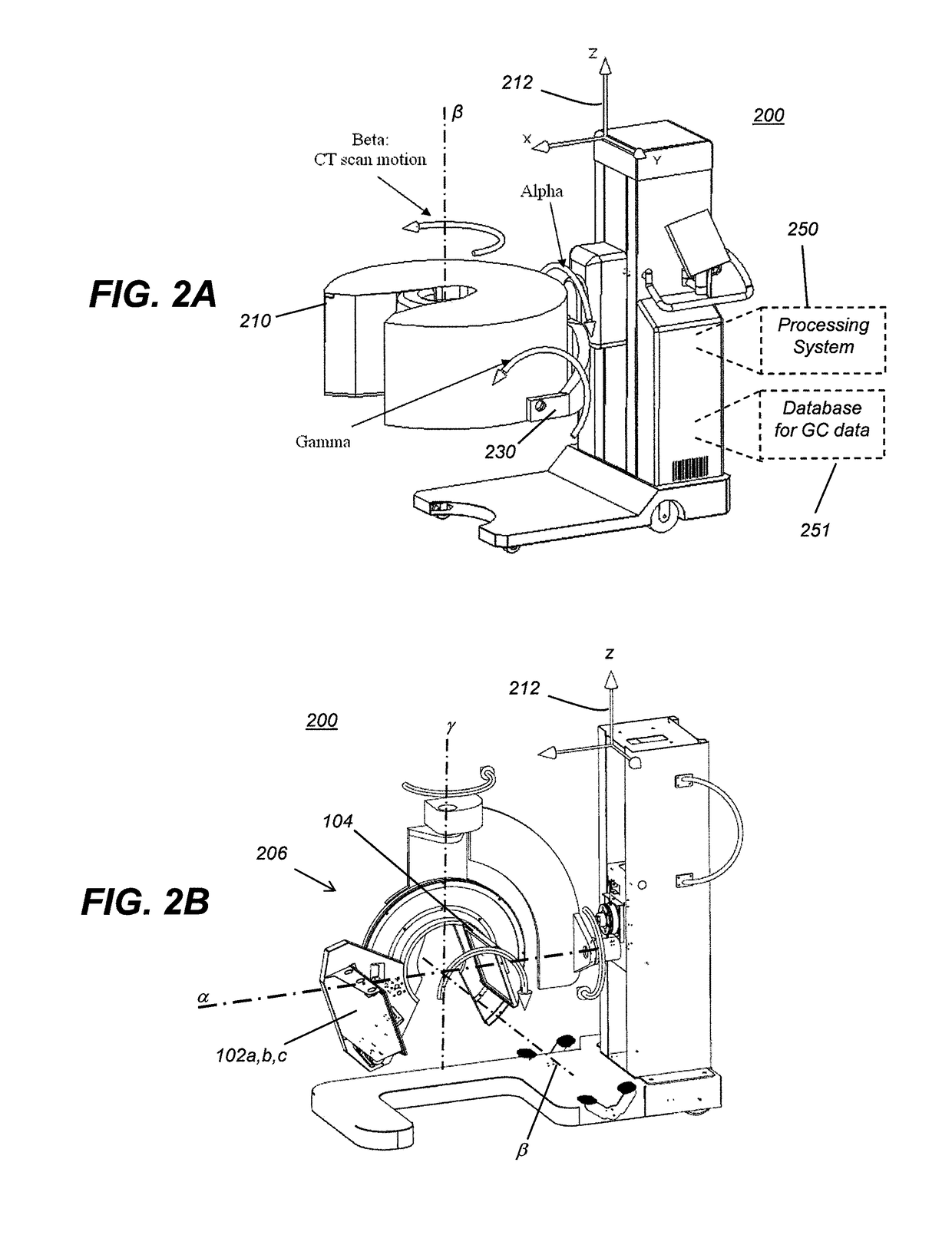
[0021]With reference to FIG. 1A there is illustrated a schematic diagram of a tomographic imaging system 100 comprising one or more radiographic energy (x-ray) sources 102a-c aimed at an object 106 to be radiographically imaged. A digital radiographic (DR) detector 104 is positioned in a known and predetermined geometric spatial relationship with the x-ray sources 102a-c wherein the object 106 to be imaged is positioned therebetween. In one embodiment, the x-ray sources 102a-c and the DR detector 104 may form a portion of a CBCT imaging system 200 (FIGS. 2A-C), whereby one or more of the x-ray sources 102a-c and the detector 104 are configured to revolve about an imaging axis β while capturing a plurality of digital projection (2-D) images of the object 106 in the detector 104, as is well known in the digital radiography arts. The captured images may be processed in, or transmitted by, the detector 104. If transmitted, the detector 104 may use wired or wireless transmission means to...


PUM


Abstract

A method of operating a tomographic imaging system whereby a plurality of radiographic images of an object are captured at a first orientation of the system's source and detector. After the radiographic images are captured and stored, geometric calibration data for the system is measured, corresponding to the first orientation of the system. A three dimensional image of the object is reconstructed using the measured geometric calibration data corresponding to the first orientation.

Description

CROSS REFERENCE TO RELATED APPLICATIONS[0001]This application is related in certain respects to U.S. patent application Ser. No. 14 / 048,599, filed Oct. 8, 2013, in the name of Litzenberger et al., and entitled EXTREMITY IMAGING APPARATUS FOR CONE BEAM COMPUTED TOMOGRAPHY; and to U.S. patent application Ser. No. 14 / 879,136, filed Oct. 9, 2015, in the name of Simon, and entitled ITERATIVE RECONSTRUCTION PROCESS which are hereby incorporated by reference herein as if fully set forth in their entirety.BACKGROUND OF THE INVENTION[0002]The invention relates generally to diagnostic imaging using tomographic imaging systems such as cone beam imaging systems to obtain volume images of patient anatomies. Three dimensional radiographic imaging techniques may be used to generate accurate volume images of patient anatomies using reconstruction algorithms during tomosynthesis and tomography image processing, such as in cone beam computed tomography (CBCT) systems using one or more radiation sourc...

Claims


Application Information

Patent Timeline
IPC IPC(8): A61B6/00A61B6/03G06T11/00
CPCA61B6/583G06T11/008A61B6/032G06T2207/30168A61B6/4007G06T2207/10081A61B6/4085G06T11/005
Inventor WEST, FRANKPACKARD, NATHAN J.
Owner CARESTREAM HEALTH INC
Why Eureka
Try Eureka