On-site calibration of array antenna systems

a technology of array antenna and array antenna, applied in the field of array antenna, can solve the problems of affecting the accuracy of array antenna, so as to achieve the effect of convenient operation

Active Publication Date: 2017-10-19
SRC INC
View PDF27 Cites 11 Cited by
  • Summary
  • Abstract
  • Description
  • Claims
  • Application Information

AI Technical Summary

Problems solved by technology

One drawback to this approach relates to the fact that a portion of the element channel (i.e., the antenna dipole elements and the ground plane) is not included in the calibration process.
Another drawback to using internal calibration couplers relates to their physical size.
Yet another drawback relates to the differences in the coupling efficiency at each element channel.
In other words, the couplers and the feed network are a source of error in and of themselves.
One drawback to this approach relates to the resolution of the attenuators and phase shifters needed for precise compensation.
In addition, the signal to or from the probe must remain stable over time (i.e. several years) and this is difficult, if not impossible, to ensure.
If the probe signal is imprecise, the compensation will also be inaccurate.
One of the drawbacks to this approach—and the previous approach—is that the system under calibration is not operating under actual operating conditions.
As a result, for example, the conventional calibration techniques outlined above cannot account for temperature variations.
It isn't always practical, however, to measure element voltage gain patterns.
Decoupling the radiating part of the antenna from the beamformer / feed to enable such element pattern measurements at best introduces errors attributed to the componentry needed to connect to a receiver.
One drawback to this approach relates to the fact that it is relatively time consuming because all columns must be measured individually.
Moreover, these types of methods are error prone because the azimuth combiner is measured separately from the columns.
Additional errors are introduced by the bench-top measurement because a “reference array” is needed to de-embed the radiating element part of the column from the beamformer part, and the connections between the reference array and instrumentation are not identical to the connections between the column array elements and beamformer.
Perhaps most importantly, once in the field, temperature variations, mechanical stresses, and so forth degrade calibration.
The problem is that the calibration does not directly indicate how the antenna pattern may have been altered in directions other than that of the probe.
As noted above, this approach has the following drawbacks: antenna element level effects are not taken into account, only the array normal signal is calibrated; and calibration is no more accurate than the monitor feed itself.
While this approach avoids the monitor feed errors, heretofore, it only provides antenna calibration in the direction of the probe.

Method used


Image

  • On-site calibration of array antenna systems
  • On-site calibration of array antenna systems
  • On-site calibration of array antenna systems

Examples


Embodiment Construction

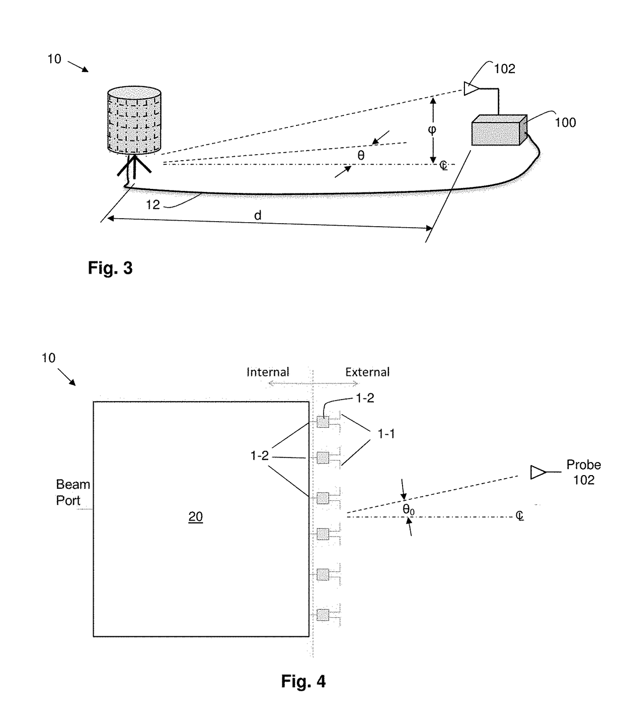
[0068]Reference will now be made in detail to the present exemplary embodiments of the invention, examples of which are illustrated in the accompanying drawings. Wherever possible, the same reference numbers will be used throughout the drawings to refer to the same or like parts. An exemplary embodiment of the radar calibration system of the present invention is shown in FIG. 3, and is designated generally throughout by reference numeral 10.

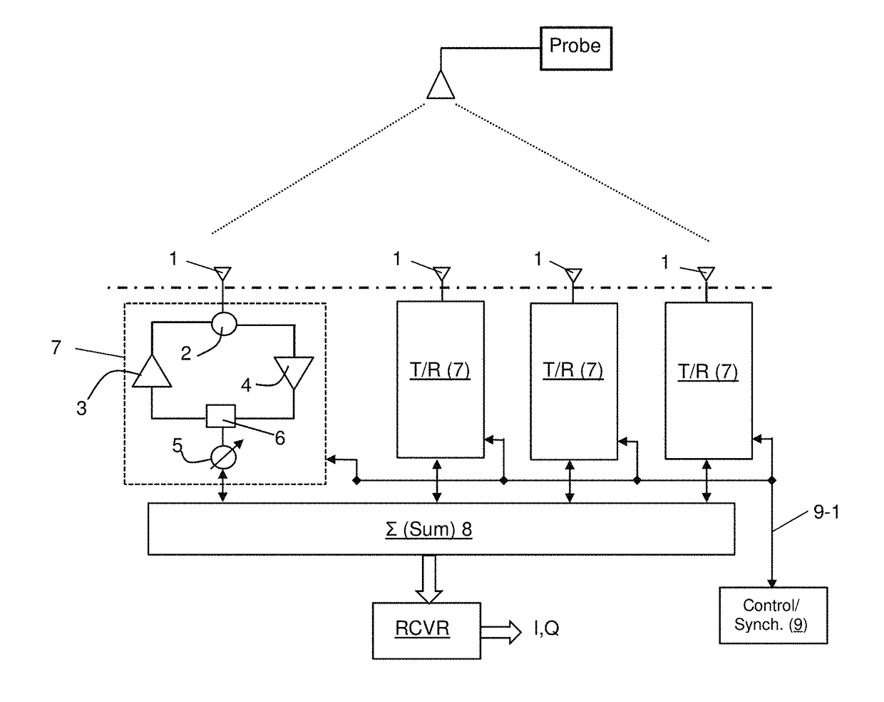
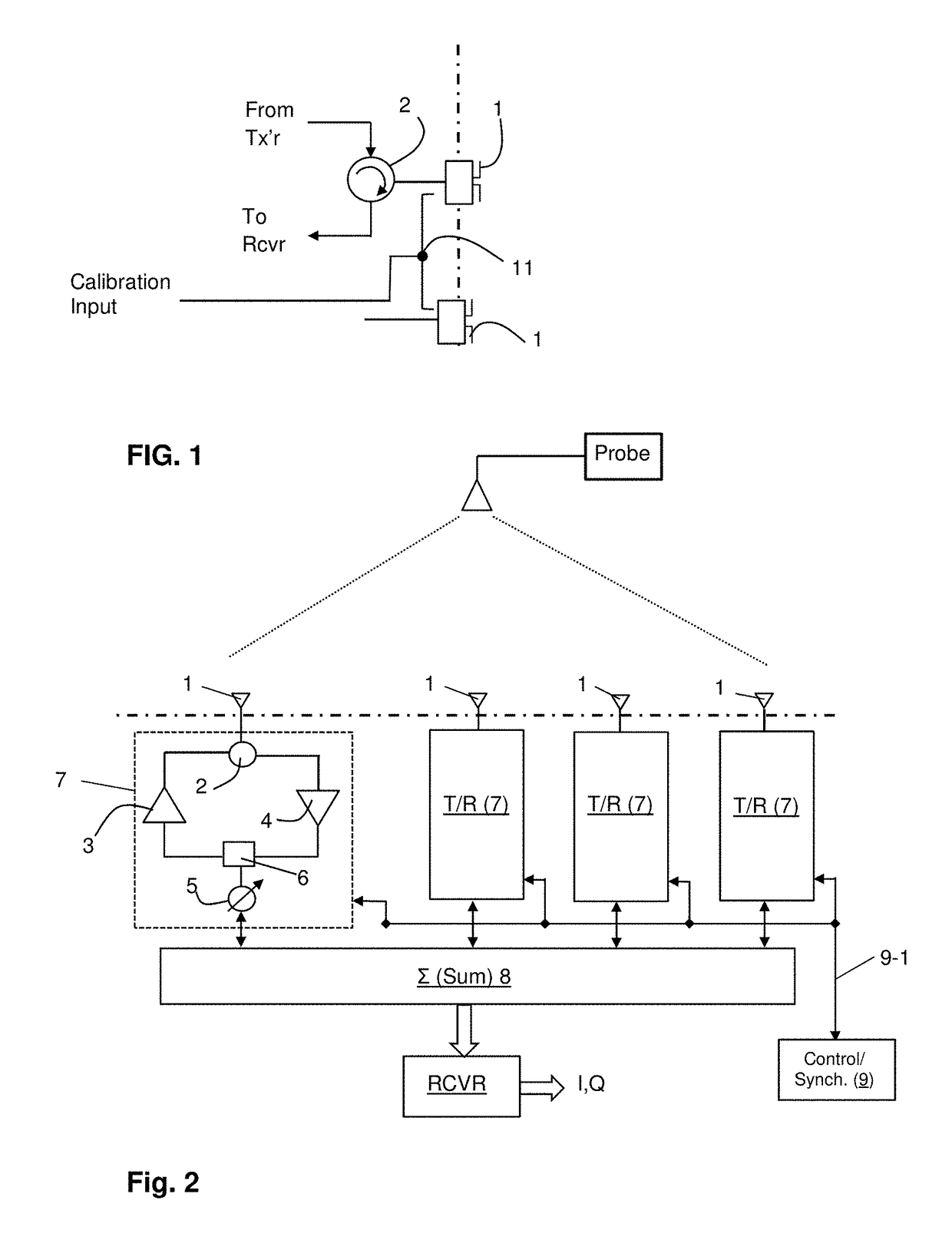
[0069]As embodied herein, and depicted in FIG. 3, a diagrammatic depiction of an array calibration set-up in accordance with one embodiment of the present invention is disclosed. The array under test 10 is coupled to a test probe 100 by a communications link 12. The array 10 is shown as a non-planar array, but it should be appreciated that the present invention may be employed in a system that includes a planar phased array antenna. The probe need only be positioned at only one well surveyed point as part of updating the calibration; thus, the lo...


PUM


Abstract

The present invention is directed to an antenna system and a method that is configured to compute calibration element voltage gain patterns as functions of a digital antenna model and a plurality of complex beamformer voltages, determine calibration through path transfer functions from the plurality of complex voltages, and remove the calibration element voltage gain patterns from the calibration through path transfer functions to determine a beamforming network transfer function. The beamforming network transfer function and the far-field element voltage gain patterns are combined to obtain a system transfer function used to revise a calibration table.

Description

BACKGROUND OF THE INVENTION1. Field of the Invention[0001]The present invention relates generally to antenna systems, and particularly to array antennas as used in radars, communications or radiometry.2. Technical Background[0002]The term radar is an acronym that stands for “radio detection and ranging.” A radar system transmits radio frequency (RF) signals in a predetermined direction (i.e., a bearing or angle-of-arrival) with the intention of contacting or illuminating moving objects (“contacts”). When the transmitted radar signal illuminates a contact, a return signal is reflected back toward the radar receiver. The return signal is detected if the return signal is stronger than any noise signals that may be present in the receiver. A contact's bearing corresponds to the direction of the transmitted radar signal because the signal travels at the speed of light. The distance, or “range,” is determined by measuring the time between signal transmission and the reception of the retur...

Claims


Application Information

Patent Timeline
Patent Type & Authority Applications(United States)
IPC IPC(8): H01Q3/26H01Q3/40H01Q3/34
CPCG01S7/4026G01S7/2813G01S13/4463G01S7/40H01Q3/267H04B7/0617G01S7/4017G01S2013/0254G01S2013/0245H04B17/12G01S13/44H01Q3/2605
Inventor SCHUMAN, HARVEY K.
Owner SRC INC
Why Eureka
Try Eureka