
Electromagnetic rotary drive and rotational device

Active Publication Date: 2017-10-19
LEVITRONIX
View PDF4 Cites 18 Cited by
  • Summary
  • Abstract
  • Description
  • Claims
  • Application Information

AI Technical Summary

Benefits of technology

The patent text explains the advantages of using a bearingless motor in pumps, stirrers, and mixers. The design features a rotor that serves as both the rotor of the electromagnetic drive and the rotor of the pump, stirrer, or mixer, resulting in a compact and space-saving configuration. The use of permanent magnets in the stator leads to a high magnetomotive force, even when only a small portion of the magnetic flux is generated by the electromagnetic drive. The specific embodiment of the stator with coil cores that have a permanent magnetic portion between two permanent magnet-free portions guides the flux paths separately through the permanent magnets and the electromagnetic drive, resulting in a large portion of the magnetic flux or even the total magnetic flux in the stator. The electromagnetically generated flux is preferred to pass through soft magnetic material such as iron or silicon iron, except for the air gaps between the rotor and stator. Overall, the patent text describes a highly efficient and effective design for pumps, stirrers, and mixers.

Problems solved by technology

Such single-use applications today frequently replace processes in which all those components which come into contact with the substances to be treated in the process previously had to be cleaned and sterilized in a complex and / or expensive manner, for example by steam sterilization, due to the very high purity demands.
If the stator is excited as customary solely by windings, that is electromagnetically, such a high magnetomotive force is impossible to realize in the mostly tight construction space of the stator with reasonable dimensions.
However, such metals represent a substantial cost factor due to their comparatively small occurrence and due to their complex and / or expensive mining and processing.
In addition, the waste disposal of such permanent magnets after a single use, for example, is frequently also associated with problems or a high effort under technical environmental aspects, whereby additional costs arise.

Method used


Image

  • Electromagnetic rotary drive and rotational device
  • Electromagnetic rotary drive and rotational device
  • Electromagnetic rotary drive and rotational device

Examples


first embodiment

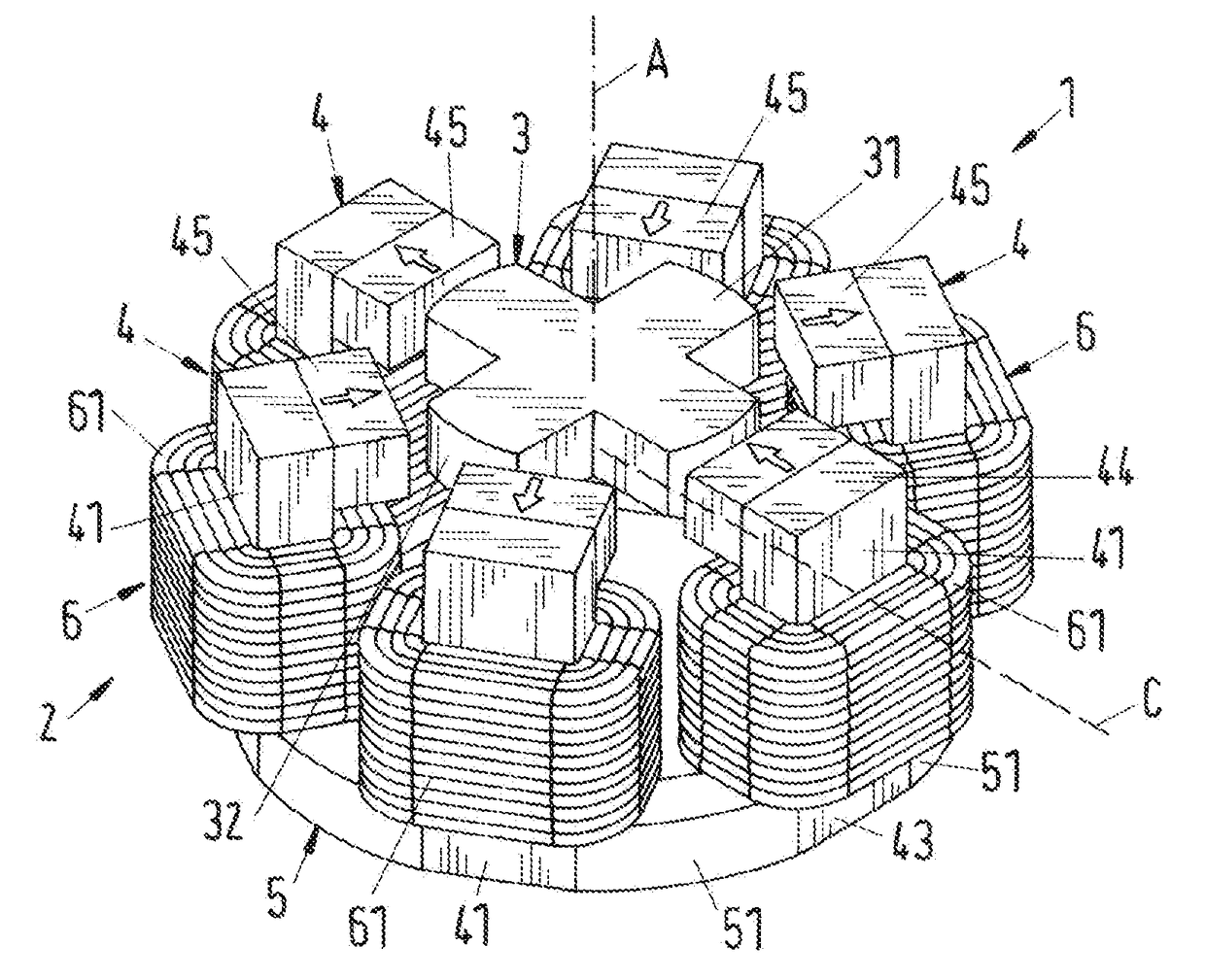
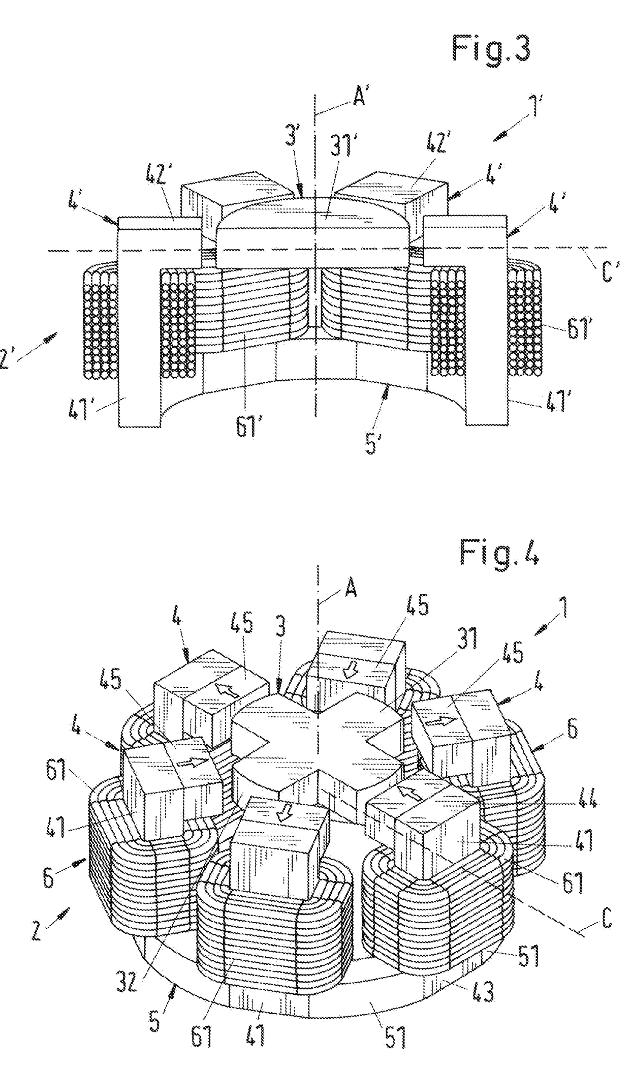
[0091]The stator 2 furthermore comprises a plurality of windings 6 for generating an electromagnetic rotational field. The windings 6 are here configured as individual coils 61 of which each surrounds one of the longitudinal limbs 41. This means that the axes of the coils 61 each extend in parallel with the axial direction A. In the first embodiment shown in FIG. 4, each longitudinal limb 41 supports exactly one coil 61.

[0092]It is therefore a further feature of the temple motor 1 that the coils 61 of the stator 2 are arranged outside the magnetic rotor plane C, beneath the magnetic rotor plane C in accordance with the representation. The coils 61 are preferably arranged completely beneath the magnetically effective core 31. The coils 61 are therefore not arranged in the plane in which the rotor 3 is driven and supported in the operating state. Unlike other electromagnetic rotary drives in which the coils of the stator are arranged such that the coil axes each lie in the magnetic ro...

second embodiment

[0121]A total of six coil cores 4 are also provided in the second embodiment and surround the rotor 3 in a circular form and equidistantly. The number of six coil cores 4 is to be understood as exemplary in this respect. A different number of coil cores 4 can naturally also be provided, for example eight or twelve or four coil cores 4, wherein an even number of coil cores 4 is preferred for technical regulation reasons. A number of six or eight or twelve coil cores 4 has proven advantageous for many applications.

[0122]FIG. 7 shows a preferred third embodiment of the rotary drive 1 in accordance with the invention in a perspective representation. For better understanding, FIG. 8 shows a section through this third embodiment in the axial direction. In the following, only the differences from the above-described embodiments will be looked at. The reference numerals in particular have the same meaning as has already been explained in connection with the embodiments described above. It i...

third embodiment

[0123]In the third embodiment, each coil core 4 comprises a transverse limb 42 that is arranged at the second end 44 of the respective longitudinal limb 41 and that extends in the radial direction, that is perpendicular to the axial direction A and thus perpendicular to the respective longitudinal limb 41. In the embodiment of the electromagnetic rotary drive 1 shown in FIGS. 7 and 8 as an internal rotor, the transverse limbs 42 extend inwardly, that is toward the rotor 3, in the radial direction. It is understood that in an embodiment of the rotary drive 1 as an external rotor (see e.g. FIG. 18), the transverse limbs 42 each extend outwardly, that is again toward the rotor 3, in the radial direction.

[0124]Each coil core 4 thus has an L-shaped embodiment, wherein the longitudinal limbs 41 form the long limb of the L that extends in the axial direction A and the transverse limbs 42 that extend perpendicular to the longitudinal limbs 41 toward the rotor 3 in the radial direction form ...


PUM


Abstract

An electromagnetic rotary drive includes a contactlessly magnetically drivable rotor that is coil-free and free of permanent magnets and that includes a magnetically effective core, and a stator by which the rotor is contactlessly magnetically drivable about a desired axis of rotation in the operating state. The stator has a plurality of coil cores of which each includes a bar-shaped longitudinal limb extending from a first end in a direction in parallel with the desired axis of rotation up to a second end, all the first ends being connected by a reflux of windings generate an electromagnetic rotational field of which each surrounds one of the longitudinal limbs. The coil cores include a plurality of permanent magnets by which a permanent magnetic pre-magnetization flux can be generated.

Description

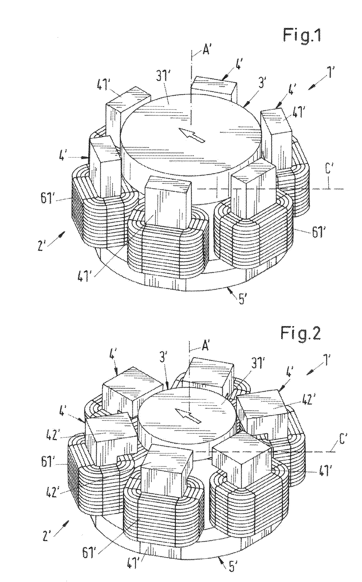
CROSS-REFERENCE TO RELATED APPLICATION[0001]This application claims priority to European Application No. 16165393.6, filed Apr. 14, 2016, the contents of which are hereby incorporated herein by reference.BACKGROUNDField of the Invention[0002]The invention relates to an electromagnetic rotary drive and to a rotational device.Background of the Invention[0003]Electromagnetic rotary drives are known that are configured as so-called temple motors. Two embodiments of a temple motor can be seen in respective perspective representations in FIGS. 1 and 2 that are known from the prior art. For better understanding, FIG. 3 shows a section through the temple motor of FIG. 2 in an axial direction. To indicate that the representations in FIGS. 1 to 3 are apparatuses from the prior art, the reference numerals are here respectively provided with an inverted comma or dash. The temple motor is characterized as a whole by the reference numeral 1′.[0004]What is characteristic about a temple motor is th...

Claims


Application Information

Patent Timeline
IPC IPC(8): H02K21/38H02K19/10A61M60/122A61M60/232A61M60/237A61M60/422A61M60/82
CPCH02K19/103H02K21/38H02K1/243H02K21/04H02K21/44A61M60/237A61M60/122A61M60/232A61M60/82A61M60/422F16C32/0497H02K7/09B01F33/4535B01F33/453H02K1/17H02K1/14
Inventor HOLENSTEIN, THOMASSCHOB, RETO
Owner LEVITRONIX
Learn More