
Combustion engine as well as method for engine braking using such a combustion engine

a combustion engine and combustion engine technology, which is applied in the direction of machines/engines, output power, non-mechanical valves, etc., can solve the problems of unwanted heating of the components of the combustion engine, and the destruction of the engine valve control without force recovery, and achieve the effect of high engine braking

Active Publication Date: 2017-10-26
FREEVALVE
View PDF3 Cites 0 Cited by
  • Summary
  • Abstract
  • Description
  • Claims
  • Application Information

AI Technical Summary

Benefits of technology

The present invention is an improved engine braking method for combustion engines that addresses previous methods' limitations. The method involves operating the engine in a two-stroke cycle during braking and filling the cylinder with high-pressure air, resulting in a braking effect that exceeds the engine's drive effect during five-stroke cycle operation. By providing air with high pressure early in the compression stroke, the method contributes significantly to the braking effect. The invention also prevents excessive heating of combustion engine components during braking and reduces energy consumption by reducing the size of engine valve springs.

Problems solved by technology

However, this engine braking effect only corresponds to a part of the drive effect of the combustion engine, at the same time as this type of engine braking above all result in unwanted heating of the components of the combustion engine.
Engine braking according to conventional type entail that the combustion engine must have engine valve springs having high permanent spring force, which is not a problem in connection with conventional camshaft actuated engine valves since the high spring force is recovered on the back side of the cam, however it is devastating for an engine valve control without force recovery.

Method used


Image

  • Combustion engine as well as method for engine braking using such a combustion engine
  • Combustion engine as well as method for engine braking using such a combustion engine
  • Combustion engine as well as method for engine braking using such a combustion engine

Examples


first embodiment

[0050]Reference is now also made to FIGS. 4 and 5, which disclose two alternatives of the invention. First of all only additions in relation to the above will be described, everything else is the same if nothing else is stated.

[0051]According to this first embodiment of the invention the combustion engine 1 comprises a controllable valve 29 arranged in the exhaust air channel 10, the storage reservoir 11 being arranged between the first outlet valve 8 and the controllable valve 29. In other words, the fluid communication between the storage reservoir 11 and the cylinder volume 6 is controlled by means of the first outlet valve 8. The storage reservoir 11 may be constituted by a part of the actual exhaust air channel 11, or alternatively may be constituted by a separate tank arranged in, or connected to, the exhaust air channel 10.

[0052]In the second alternative of the first embodiment (FIG. 5), the combustion engine also comprises a second cutlet valve 30, that is arranged in parall...

second embodiment

[0057]Reference is now made to FIGS. 6 and 7, which disclose two alternatives of the invention. First of all only differences and additions in relation to the above will be described, everything else is the same if nothing else is stated. It shall be pointed out that in these embodiments the controllable valve 29 may alternatively be constituted by an over pressure valve that opens at a predetermined pressure, however it is mentioned as being the controllable valve 29 for sake of clarity.

[0058]According to this second embodiment of the invention the storage reservoir 11 is connected to the exhaust air channel 10, the controllable valve 29 of the combustion engine 1 being arranged between the storage reservoir 11 and the exhaust air channel 10. According to the first alternative of the second embodiment (FIG. 6) the fluid communication between the storage reservoir 11 and the cylinder volume 6 is controlled by means of the controllable storage reservoir valve 12.

[0059]According to th...

third embodiment

[0062]Reference is now made to FIGS. 8 and 9, which disclose two alternatives of the invention. First of all only differences and additions in relation to the above will be described, everything else is the same if nothing else is stated.

[0063]According to this third embodiment of the invention the storage reservoir 11 is connected to the intake air channel 9 via a check valve 34, which allow fluid flow from the intake air channel 9 to the storage reservoir 11. According to the first alternative of the third embodiment (FIG. 8) the fluid communication between the storage reservoir 11 and the cylinder volume 6 is controlled by means of the controllable storage reservoir valve 12.

[0064]According to the second alternative of the third embodiment (FIG. 9) the fluid communication between the storage reservoir 11 and the cylinder volume 6 is controlled by means of the second inlet valve 32, whereupon the check valve 34 and the storage reservoir 11 are arranged in the second intake air cha...


PUM


Abstract

Disclosed is a combustion engine and method for engine braking therein including an intake air channel having a first pressure, a first inlet valve between the intake air channel and the cylinder volume, an exhaust air channel having a second pressure, a first outlet valve between the cylinder volume and the exhaust air channel, and a storage reservoir having a third pressure higher than the first and second pressures, the storage reservoir being arranged in controllable fluid communication with the cylinder volume. The method takes place during two-stroke cycle and includes: displacing the piston from upper dead centre (UDC) towards lower dead centre (LDC), keeping the first inlet valve open during at least part of the travel from UDC to LDC, displacing the piston from LDC towards UDC, and keeping the fluid communication between the storage reservoir and cylinder volume open during at least a part of such travel.

Description

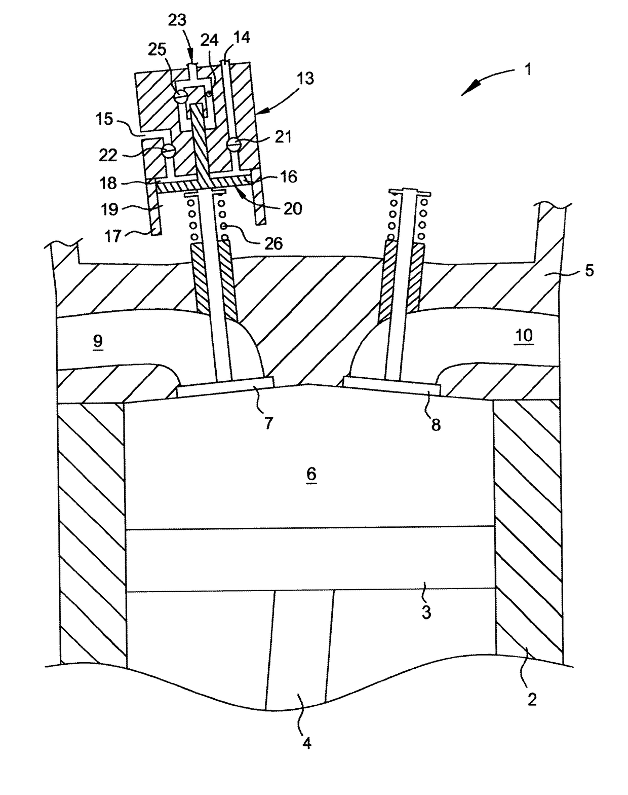
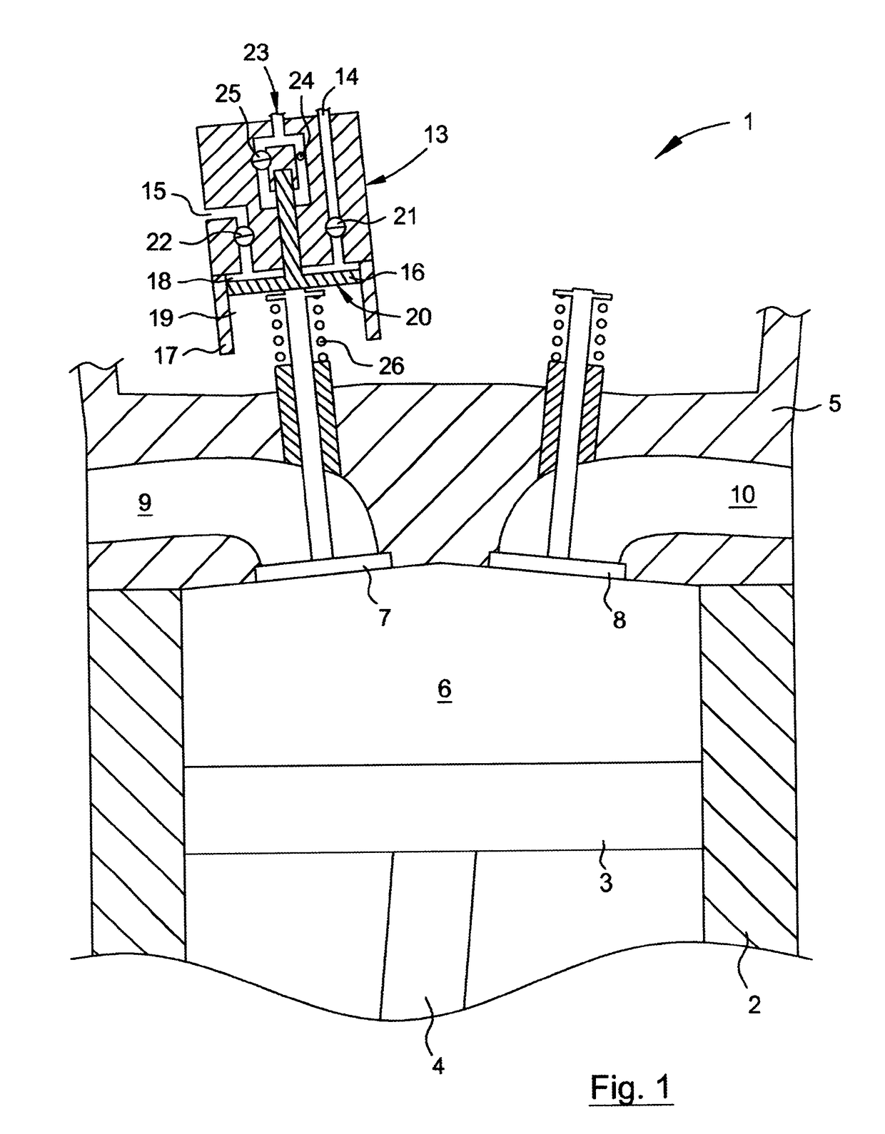
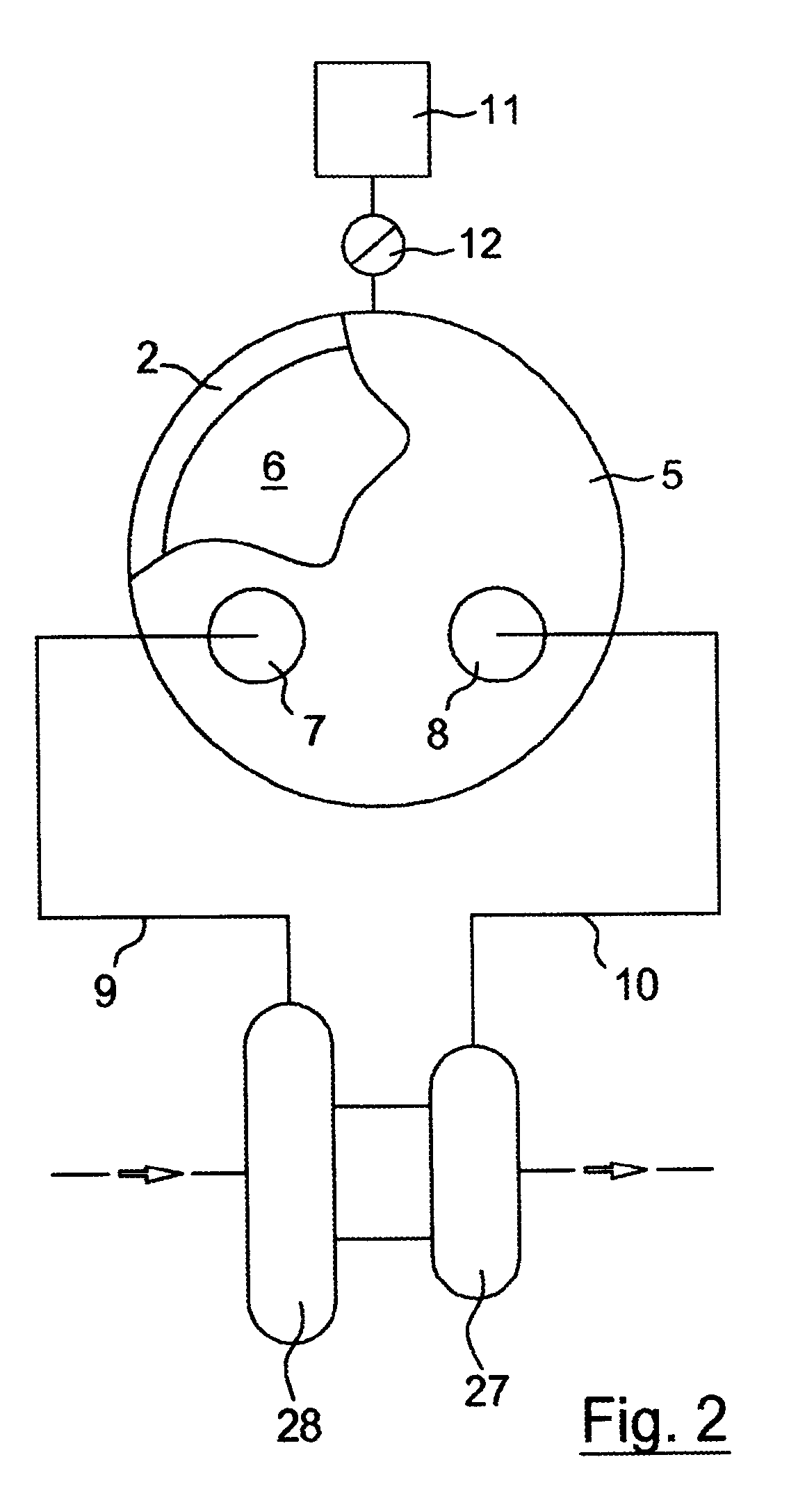
TECHNICAL FIELD OF THE INVENTION[0001]The present invention relates in general to a combustion engine as well as a method for engine braking using such a combustion engine, typically being arranged in a so-called heavy vehicle. The combustion engines concerned are above all camshaft free piston engines, which are also known under the term “engines having free valves”. The present invention relates specifically to a method for engine braking in a combustion engine comprising at least one cylinder having a cylinder volume and a piston displaceable in said cylinder, an intake air channel having a first pressure P1, a first inlet valve arranged between the intake air channel and the cylinder volume, an exhaust air channel having a second pressure P2, a first outlet valve arranged between the cylinder volume and the exhaust air channel, and a storage reservoir having a third pressure P3 that is higher than said first pressure P1 and said second pressure P2, the storage reservoir being ar...

Claims


Application Information

Patent Timeline
Patent Type & Authority Applications(United States)
IPC IPC(8): F02D13/04F02D13/02F02B75/02F02B37/22F02B21/00F01L9/10
CPCF02D13/04F02B37/22F02B75/02F02B2075/025F02D13/0203F02D13/028F02B21/00F01L13/06F02D13/0253F02D13/0257F02D13/0276F02B37/00F01L9/10F02B21/02F02D17/023
Inventor HOGLUND, ANDERSCARLSON, URBAN
Owner FREEVALVE
Learn More