
Powder core, manufacturing method of powder core, inductor including powder core, and electronic/electric device having inductor mounted therein

a manufacturing method and powder core technology, applied in the direction of cores/yokes, inductances, magnetic bodies, etc., can solve the problem of not performing dc superposition characteristics evaluation, and achieve excellent dc superposition characteristics, low loss, and easy to cope with a high current

Active Publication Date: 2017-10-26
ALPS ALPINE CO LTD
View PDF5 Cites 6 Cited by
  • Summary
  • Abstract
  • Description
  • Claims
  • Application Information

AI Technical Summary

Benefits of technology

The present invention provides a powder core for an inductor that improves DC superposition characteristics and reduces core loss. The powder core contains a mixture of a crystalline magnetic material powder and an amorphous magnetic material powder, where the particle size distribution of both materials is adjusted. This results in a nonlinear improvement of the DC superposition characteristics and a reduction of core loss. The manufacturing process, inductor, and electronic / electric device with the inductor are also provided.

Problems solved by technology

However, in Japanese Unexamined Patent Application Publication No. 2010-118486, evaluation of DC superposition characteristics is not performed.

Method used


Image

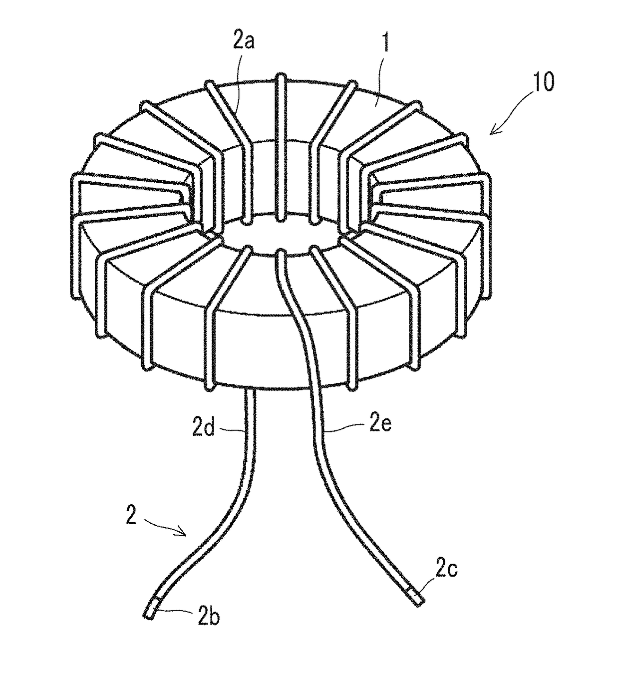
  • Powder core, manufacturing method of powder core, inductor including powder core, and electronic/electric device having inductor mounted therein
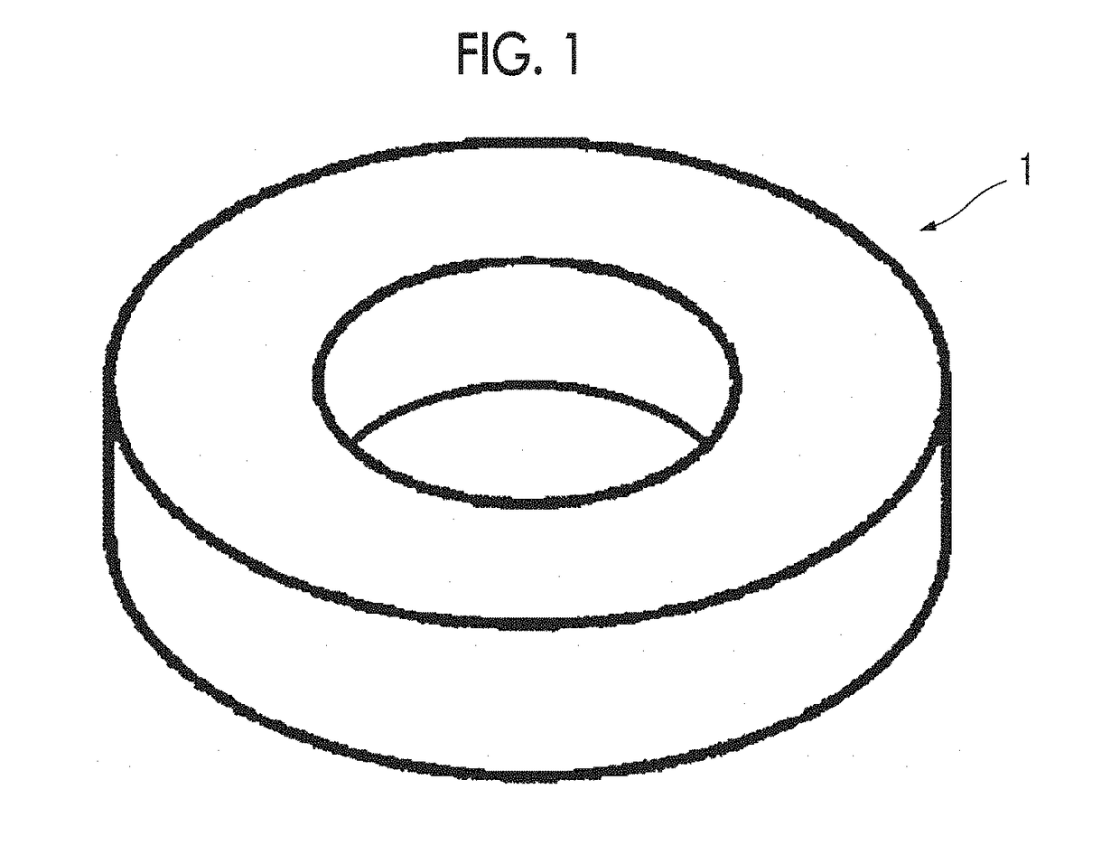
  • Powder core, manufacturing method of powder core, inductor including powder core, and electronic/electric device having inductor mounted therein
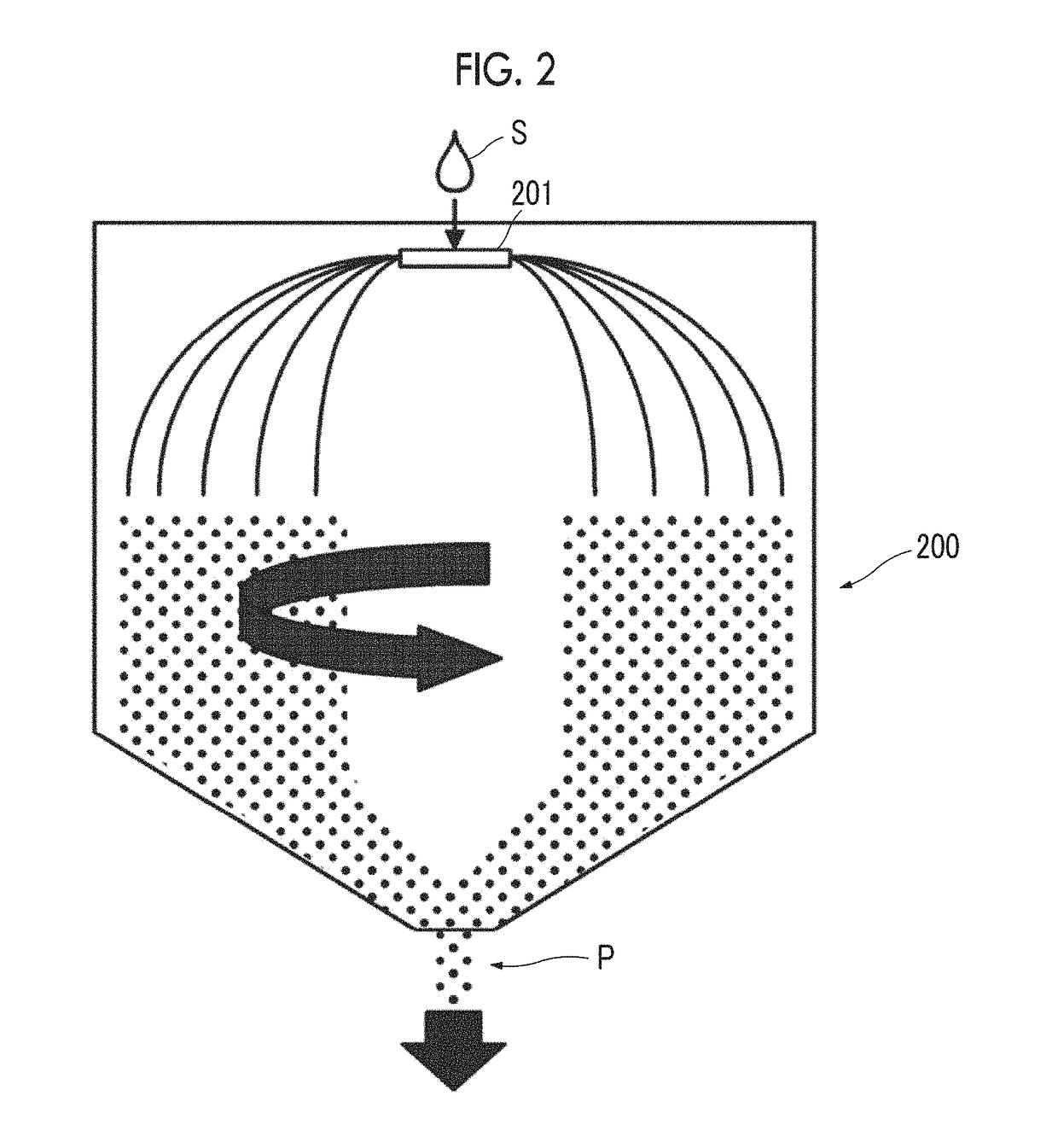
  • Powder core, manufacturing method of powder core, inductor including powder core, and electronic/electric device having inductor mounted therein

Examples


embodiments

[0110]Hereinafter, the present invention will be described in more detail with reference to examples and the like, but the scope of the present invention is not limited to the examples and the like.

example 1

Production of Fe-Based Amorphous Alloy Powder

[0111]Raw materials were weighed so as to achieve a composition of Fe71 at % Ni6 at % Cr2 at % P11 at % C8 at % B2 at %, and powders of five types of amorphous magnetic material (amorphous powders) having different particle size distributions were produced using a water atomization method. The particle size distributions of the powders of the obtained amorphous magnetic materials were measured as volume-based distributions using “Microtrac particle size distribution measuring apparatus MT3300EX” manufactured by Nikkiso Co., Ltd. The particle size (median diameter) D50A at 50% on a cumulative particle size distribution from the small particle size side in the volume-based particle size distribution was 5 μm. In addition, as a powder of a crystalline magnetic material, a powder which is made of a Fe—Si—Cr alloy, specifically, an alloy having a Si content of 6.4 mass % and a Cr content of 3.1 mass % and including Fe and impurities as the rem...

examples 2 to 10

[0124]As shown in Table 3, using magnetic powders in which the particle size of a powder of an amorphous magnetic material, the composition of a powder of a crystalline magnetic material, a surface treatment, and a particle size are different from those of the magnetic powders used in Example 1, toroidal cores including powder cores were obtained in the same manner as in Example 1. In addition, the powder of the amorphous magnetic material used in Example 10 was produced by an atomization method in which gas atomization and water atomization are continuously performed. The column of D50C in Table 3 displays the particle size (median diameter, unit: μm) which is at 50% on a cumulative particle size distribution from the small particle size side in a volume-based particle size distribution obtained by measuring the particle size distribution of the powder of the crystalline magnetic material as a volume based distribution using “Microtrac particle size distribution measuring apparatus...


PUM


Abstract

A powder core includes: a powder of a crystalline magnetic material; and a powder of an amorphous magnetic material, in which a median diameter D50A of the powder of the amorphous magnetic material is 15 μm or less, and satisfies the expression: 1≦D50A / D50C≦3.5 with respect to a median diameter D50C of the powder of the crystalline magnetic material.

Description

CLAIM OF PRIORITY[0001]This application claims benefit of Japanese Patent Application No. 2016-087549 filed on Apr. 25, 2016, which is hereby incorporated by reference.BACKGROUND OF THE INVENTION1. Field of the Invention[0002]The present invention relates to a powder core, a manufacturing method of the powder core, an inductor including the powder core, and an electronic / electric device having the inductor mounted therein. In this specification, an “inductor” is a passive element provided with a core material including a powder core and a coil, and includes a concept of a reactor.2. Description of the Related Art[0003]A powder core used in an inductor of a booster circuit of a hybrid vehicle or the like, a reactor used in power generation and substation facilities, a transformer, a choke coil, and the like can be obtained by compacting a soft magnetic powder. An inductor including such a powder core is required to have both a low core loss and excellent DC superposition characterist...

Claims


Application Information

Patent Timeline
IPC IPC(8): H01F27/255H01F27/29H01F27/28H01F1/153H01F1/147H01F41/02
CPCH01F27/255H01F1/14741H01F1/14791H01F27/2823H01F41/0246H01F27/29H01F1/153H01F1/26H01F3/08H01F17/04H01F17/062H01F2017/048
Inventor NAKABAYASHI, RYOKOJIMA, AKINORIABIKO, SEIICHISATO, KEIICHIROSATO, AKIRAMIZUSHIMA, TAKAO
Owner ALPS ALPINE CO LTD
Learn More